


February 16, 2017
In recently years, more and more data centers and server rooms feature high density and large capacity, in which there are a large number of copper or fiber patch cables used for connecting the whole network. In order to ensure the performance of the whole network, there is no doubt that these patch cables should be connected with no error. Any improper cable management would directly result in cable damage and network failure that can cause data transmission error, performance issue and system downtime. But the fact is that the work of managing these massive patch cables is a quite difficult task, which is easily in error. Then what can we do to achieve good cable management and ensure network performance? This paper will mainly study the cable lacing bar, which is designed for achieving good cable management.
It is well known that cable ties (like nylon cable ties and velcro cable ties), patch panels (like copper patch panels and fiber patch panels) and J-Hook enables better cable management in high density network, which can be also found it in my last paper. Except these tools, is there any other tool that can also achieve good cable management? The answer is cable lacing bar in this paper, which is as important as the previous three tools mentioned above.
The cable lacing bar, also known as lacer bars, is a common kind of cable management tool, made of metal material, which offers support and and management of the massive patch cables. With the use of cable lacing bar, the pressure created by the cable connections can be greatly relieved, the bend radius of the patch cable can be stably controlled and the cabling can be highly improved to a neat one. At present, there are various kinds of cable lacing bars with different features to satisfy the increasing requirements of cabling network, for instance, round lacing bars, rectangular lacing bars, round lacing bars with Offset and l-shaped lacing bars, etc. For the structure of common cable lacing bar, you can learn it from the following figure.
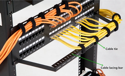
In general, the width of the cable lacing bar is always 19 inches, while its height can be alternative, 1U or 2U. It can be mounted above, below, behind, or in front of your network devices, easily found in racks (between switches and patch panels) or enclosures. As for its practical application, you are highly suggested to bind the patch cables to the cable lacing bar by the use of cable ties like black velcro cable ties in the figure above. You only need to mount the cable lacing bar to the rack, and then use the cable tie to bind the patch cables to the cable lacing bar.
What makes the cable lacing bar so widely used for managing the patch cables? Compared to other cable management tools, what are the advantages of the cable lacing bar? Firstly, using the cable lacing bar to manage the patch cables can greatly save space, because it uses less than 1U space, or doesn’t occupy any space if installed in front of or behind your network device. Hence, the valuable space can be saved for installing other network devices. Secondly, there are numerous cable lacing points, almost covering the whole cable lacing bar, which enables easier cabling. Thirdly, the cable lacing bar can relieve the strain of cables which plays an important role in high density cabling network. Fourthly, it can promotes the bend radius of the patch cables, so that the risk such as slower data transmission rates or broken patch cables can be reduced or even avoided.
As we move to more and more complicated network, the cable management takes an much more important role than ever before. With the advantages of relieving pressure created by the cable connections, promoting the bend radius of the patch cables and saving space, the cable lacing bar is an ideal choice for efficient and neat cable routing. Hence, it would be better to choose a suitable kind of cable lacing bar to manage your patch cables if your network features high density and large capacity.
Posted by: katherinewangfs at
03:23 AM
| No Comments
| Add Comment
Post contains 703 words, total size 5 kb.
February 11, 2017
As we move to more and more complicated network, the cable management becomes much more difficult than ever before. If there is something wrong in the cable deployment or management, the system downtime may occur that directly affects the productivity and efficiency of the system. Meanwhile, if the cable is not well managed, the whole system will look very dirty, disorderly and bad. In order to solve these issues, several solutions are put forward to make the cable management faster and easier and maximize the performance of the system, such as, zip tie, patch panel, J-Hook, etc. In this paper, it will mainly study these commonly used cable management tools for deploying a sophisticate, but stable and tidy cabling network.
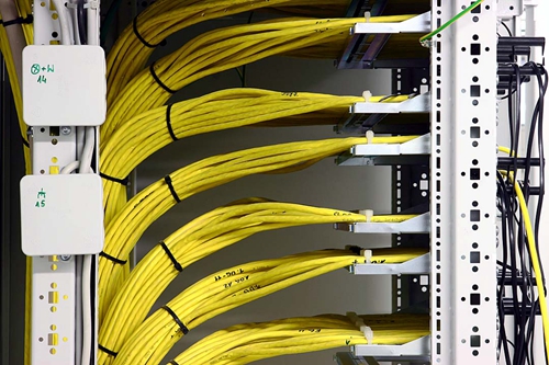
Zip tie can be also called cable tie or wire tie that functions as a fastener for holding cables or wires together. Compared to other cable management tools, zip tie is very cheap and easy to be used. Hence, it can be easily found in a wide range of applications for managing the cables. At present, there are various kinds of zip tie available on the market, for instance, velcro zip tie that can be reusable and adjustable to support frequent moves, adds, and changes of cables, and the stainless steel zip tie that can be used in the extremely cold, hot or corrosive application. To better know the function of the zip tie, you can learn it from the following figure, in which the black zip ties play a vital role in better cable management.
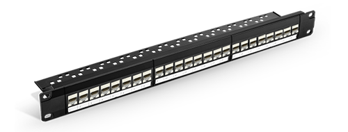
Patch panel, also referred to as patch bay, patch field or jack field, is a crucial unit in the wired network that consists of a number of similar or same jacks, with the aim of connecting and routing circuits for monitoring, interconnecting, and testing the circuits in a convenient, flexible way. In general, it can be simply divided into fiber patch panel and copper patch panel. Although the fiber patch panel is more expensive than the copper one, both of them have their own advantages and disadvantages. Therefore, you can just choose the more proper one to deploy your cabling network, enabling the ease of cabling network management and avoiding the data transmission error or failure. In addition, here offers a figure that shows the structure of 24 port Cat 6 patch panel for your reference.
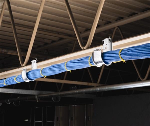
As we all know that there are some widely used tools for hanging and supporting the cable bundles like zip tie and brindle ring. However, once these narrow-base kinds of fasteners exceed the bend radius of the cables, it may cause network failure. Hence, experts turn to J-Hook to solve this problem, as a cost effective solution. What should be noted it that the horizontal cabling tray is also designed for dealing with this problem, but it is not recommendable for its higher cost and taking more time for installation than J-Hook.
J-Hook, usually made of galvanized steel or sometimes of plastic polymers, can be installed in both indoor and outdoor. From its name, it is easy to learn that its structure is like the letter "Jâ€. You can also learn it from the following figure. This design of a wide base with smooth, rounded corner has the ability to effectively eliminate the potential for snags during installation, while preventing the cable bundle from stress as shown below. Due to the advantages mentioned above, it is highly suggested to choose J-Hook to manage the cable bundle.
There is no doubt that well organized cable management can make the network maintenance easier and faster, ensure the maximum performance of the network and reduce or eliminate the network connection errors and failure. It is really worthy choosing the proper cable management tools for better cable management. In addition, except for the three tools mentioned above, there are other kinds of tools like cable manager and cable lacing bar can be also used to manage the cable in better organization. Hope the information in this paper would be useful for you to deploy a neat and high performance network.
Posted by: katherinewangfs at
02:50 AM
| No Comments
| Add Comment
Post contains 692 words, total size 5 kb.
February 08, 2017
It is well known that there are various kinds of connectors used to terminate the fiber optic patch cables, such as LC, SC, FC and MTP/MPO connector. As for terminating the copper based patch cables widely applied in home wired network, there are also several RJ-style connectors published like RJ11, RJ12, RJ21, RJ35 and RJ45 jack, etc. Among these jacks, the RJ11 and RJ45 jack are the most commonly used jacks that have common in appearance, which may be not easy to tell. Since the RJ45 jack is specially designed for terminating the Ethernet patch cable like Cat 5e cable and Cat 6 cable, do you wonder that can the Cat 5e cable or Cat 6 cable be also terminated by RJ11 jack? Let’s study the RJ11 and RJ45 jack information and find the differences of these two jacks, then seek the answer.
"RJ†is the acronym of "registered jackâ€, which is a standardized telecommunication network interface designed to connect voice and data equipment to a service provided by a local exchange carrier or long distance carrier, first published by the Bell system and managed by the Federal Communication Commission(FCC). As for the number 11 and 45, they stand for different types of the registered jacks for easier and better identification.
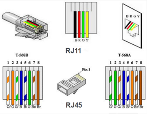
RJ11 jack, sometimes a 6P2C (6-position, 2-conductor) connector but mostly a 6P4C connector, is specially applied for telephone lines, while RJ45 jack is a 8P8C modular connector used for terminating twisted-pair cables in Ethernet network. In a typical 6P4C RJ11 jack, only four out of the six positions are generally used to terminate phone lines and the rest two are idle, but the eight positions in the RJ45 jack will be taken fully use of, four for sending and receiving data and the other four for other technologies or power networking devices, as shown in the following figure. If you want to use these two types of jacks to terminate the telephone line or the Ethernet cable, please do it in accordance with the instructions for correct terminations. Besides, it should be noted that the Ethernet cables like Cat 5e cable and Cat 6 cable can be also referred to as RJ45 cables since they can be terminated by the RJ45 jacks.
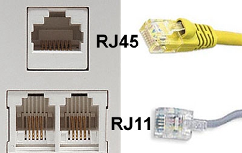
Although the RJ11 and RJ45 Jack seems very similar in appearance, but they do differ from each other in the structure. Firstly, it is obvious that there are differences in their internal structures. If you check the jacks which are connected with wires, you’ll find that there are four wires in the RJ11 jack but eight wires in the RJ45 Jack. As a result, the RJ45 Jack is generally bigger than RJ11 jack. Secondly, an typical RJ11 jack has six pins but only four of the pins in the middle are participated to connect the four wires, while there are eight pins in an RJ45 jack and both of them are used for cable termination.
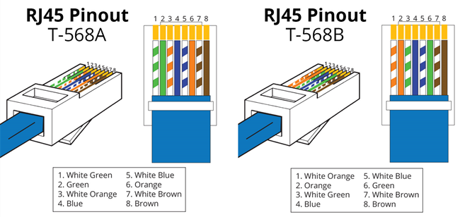
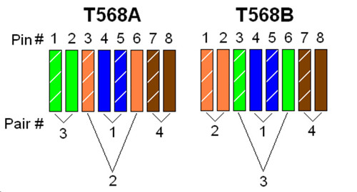
Meanwhile, these two jacks have different wiring schemes, which you can learn from the figure below. As for the wiring scheme of the RJ11 jack, you can take the POTS (plain old telephone lines) residential telephone wiring as a typical example that generally contains two pairs of wires, which are designed for two separate telephone lines. And the center pins (red and green) contain the first telephone line, while the black and yellow pins contain the second one. As for the RJ45 jack, there are two wiring schemes, T-568A and T-568B, each of which can be applied in making cross-over cable or straight-through cable. A cross-over cable is terminated with an RJ45 jack used T-568A wiring scheme in one end of the cable and another RJ45 jack used T-568B wiring scheme in the other end, while the straight-through cable is terminated with two RJ45 jacks with the same wiring scheme, T-568A or T-568B.
Moreover, the biggest difference between these two jacks is their application. As for the RJ11 jack, it is the cable connector that is used in telephone sets, ADSL, and modem cables, etc. However, the RJ45 jack is designed with the aim of terminating Ethernet patch cable in networking, where you connect computers or other network elements to each other.
After knowing the basic information of the RJ11 and RJ45 jack and analyzing the differences between these two kinds of jacks, it is simple and clear that neither Cat 5e cable nor Cat 6 cable can be terminated with the RJ11 jack. Why? As mentioned above, the RJ11 jack is smaller than RJ45 jack and there are only six pins to terminate the wires in the Cat 5e cable or Cat 6 cable. Therefore, if we use the RJ11 jack to terminate the Ethernet patch cable that generally has eight wires, there will be two wires that can’t be terminated and work normally. What’s more, these two kinds of jacks are designed for different applications. As the RJ11 jack is used for terminating telephone line and RJ45 jack is to terminate Ethernet patch cable in networking, only choosing the proper jack can the performance of the telephone line or the Ethernet patch cable can be ensured.
Posted by: katherinewangfs at
09:38 AM
| No Comments
| Add Comment
Post contains 896 words, total size 6 kb.
February 05, 2017
As the network develops fast, the form of the network is gradually migrated from wired connection to wireless connection, meeting the increasing needs of the network. Does the wireless connection perform better than the wired one? Are you still hesitating over which connection should be choose to deploy your network? In this paper, it will mainly study the basic information of the wired and wireless connection and find which one is better by comparing these two kinds of network connection, giving you the answer you may care about.
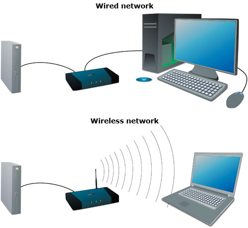
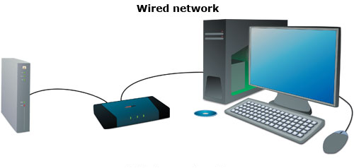
As their names imply, the wired network is deployed by using the network patch cable to connect all the devices in the wired network, while the wireless network utilizes radio waves and/or microwaves to sustain interaction channels linking computers, as shown in the following figure. Generally, both of the two forms of network have their own features, which will be introduced below.
In a wired network, network patch cable is taken full use of to connect one computer with another one or the central device in the network, and there are also other vital devices required like network adapter, hub, switch, or router to deploy further connection. As for the operation, the wired network always use the dial-up way to connect to the Internet and the computer hosting the modem has the ability to administer the Internet Connection Sharing or similar software to share the connection with every other computers on the same wired network. Compared with the wireless network, it will use broadband router that allows easier sharing of cable modem or DSL Internet connections, furthermore the broadband router often includes built-in firewall.
As for the wireless network, it is an additional recent substitute to the wired network that depends on copper and/or fiber optic cabling, which can be deployed easier and faster than the wired one. In its working process, the data is transmitted by radio waves and/or microwaves instead of through the copper and/or fiber optic patch cable. Although the cost for wireless deployment is high, this kind of network is promptly acquiring popularity for home networking because of its convenience. In addition, the most gratifying thing is that the prices of wireless commodities continue to fall as the wireless technology advances fast in recent years.
There is no doubt that the wireless network is very easy to deploy which makes it more and more popular recently. However, there are still many people who would like to choose the wired connection for their network. Why? Doesn’t the wireless network operate better than the wired one? What’s the advantages and disadvantages of these two kinds of network?
When talking about the advantages of the wired network, it is not very difficult to find that the wired network transfers the data information more swiftly and performs more securely and stably than the wireless one. Meanwhile, the devices to deploy the wired network are also not so expensive as that of the wireless one. If one cannot afford the cost for the wireless network deployment, the wired network is still a very good choice. Besides, most of the computers on the market have the wired network adapters that makes the wired network deployment convenient.
However, there are also some disadvantage that should be paid attention to when deploying the wired network. First and foremost, running the wires from one room to another within the home can be a difficult task and the network patch cables would be easy to disorganized in the installing process. And when one network patch cable in the network disconnects or becomes faulty consequently, it will cause the whole connection to fail. Furthermore, if more computers are needed to be connected to the wired network, it may result in unexpected expense. What’s worse, if it run out of the connections on your network, it could slow down the network.
After knowing the advantages and disadvantages of the wired network, let’s talk about the same topics of the wireless network. As for its advantages, it would be very neat and clean without untidy network patch cables and of high flexibility around the home for the connections around the house within a limited range. Meanwhile, it is very easy to be deployed. Even if you haven’t a great deal of networking experience, you can set up a wireless network by yourself very fast. Also, there are three main disadvantages if you choose to deploy the wireless network. Firstly, the biggest drawback of setting up a wireless home network is the high cost as mentioned above. Secondly, the potential for radio interference due to weather, other wireless devices, or obstructions like walls exits, which may make the connection wrong or failed. Thirdly, it is not so reliable as the wired network. Once one major section like the router breaks down, the whole network will be affected.
The wired network transfers the data information more swiftly, performs more securely and stably and costs lower than the wireless network, although it is not so neat, flexible and easy to deploy as the latter one. If you want to own a fast, secure and stable network, you are highly suggested to deploy the wired connection for your network. Besides, Ethernet cable for sale at FS.COM can meet your requirement to deploy the wired network, such as, cat 5e, cat 6, cat 6a and cat 7 cable. Of course, if you’d like to own a very neat network, the wireless network is very suitable for you that can be deployed very fast.
Posted by: katherinewangfs at
04:26 AM
| No Comments
| Add Comment
Post contains 937 words, total size 7 kb.
January 20, 2017
Although the wireless network becomes more and more popular for its convenience, most of our home still deploy wired connections with copper based devices that can work faster and more stable. Every so often, we get questions from people who plan to deploy copper based networks in their homes. The most frequent question we get is, "how to fast build a copper network at home?" Considering that, the following will give detailed instructions for building a copper home network in a very fast and smooth manner.
As the copper based network has an important place in the our daily life, it is very necessary to know the steps for deploying our own copper based network that is much easier than that of the fiber based network. Of course, before deploying, you should consider your requirements for the copper based network, such as, easier access to broadband and WiFi, higher network performance. Then let’s study the step by step instructions for building a copper network at home.
Bringing the Service Provider Distribution Cable to Your HomeNowadays, the distribution point of copper network cable or fiber optic cable is always installed inside or near the building by the broadband service provider, offering service for each house of the building. In some old buildings, the cables between the end users and distribution point are still copper based, while fiber optic based cables are usually used in the new buildings. If you are living in a new building with fiber optic based distribution point, then you need a ONU (Optical Network Unit) for converting the optical signals into electrical signals and distribute the signals to different ports and home devices. Hence, the service provider distribution cable can be brought to your home. At present, there are various ONUs and routers available on the market, supporting WiFi and satisfying various port requirements. If your home is not very big, you just need to choose one ONU or router for your home network.
Wiring the Whole Connection for Your HomeAfter introducing the service provider distribution cable to your home, you should decide how many ports your home network requires and how many devices should be connected to the network, which is very important for owning a home wired network with great broadband access. Due to the good preparation, you can do the whole home wiring smoothly without any delay. The following figure shows an example of the whole home wiring that connects the bedroom, living room, office and dining room of this house to the network for your reference.
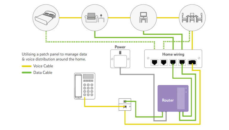
From the figure above, you can learn that there are several kinds of devices, such as, televisions and telephone, connected to the home wired network for better and smarter performance, which is also know as smart home. For instance, the voice cable is used for connecting the telephone to the network, so that the phone calls would be not missed by the house owner. Besides, other devices like air condition, light control device can be also connected to the home wired network for living in a smart home.
As for the types of the copper cables used for the connections between the network and the home devices, the Cat 5e and Cat 6 Ethernet cable are most commonly used copper based patch cables at present that completely satisfy the requirements of your network. However, the Cat 6a and Cat 7 Ethernet cable are more recommendable with higher performance which are capable of meeting the requirements for both now and future.
Terminating the Copper Cables and Finishing the Whole DeploymentThe third step is to terminate the copper cables that used for the whole connection, which plays an important role in deploying a secure and reliable wired home network. In general, the copper patch cable is suggested to be terminated at the wall plate port and a length of RJ45 copper network patch cable should be used for connecting the port with target device, thereby the whole deployment of home network can be finished.
This paper mainly studies the process of how to fast build a copper network at home, which is very useful for people who plan to deploy a copper home network for better performance. In strict accordance with the step by step instructions, you can easily and fast deploy your wired home network. Except that, choosing the most suitable patch cable also can’t be ignored for good broadband access. You can choose one of the most suitable patch cable from the mentioned above Cat 5e, Cat 6, Cat 6a and Cat 7 Ethernet cable to meet the requirements of your network.
Posted by: katherinewangfs at
07:14 AM
| No Comments
| Add Comment
Post contains 781 words, total size 6 kb.
January 18, 2017
With the rapid development of the network technology, the network deployment becomes much more complicated than ever before to satisfy the increasing network needs. In order to deploy the the complicated cabling network in a tidy, fast and correct manner, the patch panel is designed to better manage the patch cables in the network, which can be divided into two types, the copper patch panel and the fiber patch panel. To avoid the connection errors and making the cabling network flexible, reliable and neat, this paper will mainly introduce some commonly used types of the copper patch panel that may be helpful for you to pick the most suitable one for your cabling network.
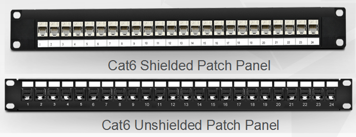
While the copper patch panel has made a great contribution to the complicated cabling network as a cost effective solution, the type of the copper patch panel has become more and more diversified, such as, shielded and unshielded patch panel, flat and angled patch panel, common and high density patch panel, classified according to the designed aspect. The following will discuss the details of these four types of commonly used copper patch panels.
Shielded vs. Unshielded Patch PanelSince the performances of the shielded and unshielded patch panel are different from each other, you should consider that should the patch panel be shielded or unshielded to fit your network before ordering the copper patch panel. Besides, you may also wonder that can you use the shielded patch cable with an unshielded patch panel or the unshielded patch cable with a shielded patch panel? Let’s explore these questions and seek the answers.
There is no doubt that the shielded patch panel performs higher than the unshielded one, because the shielded feature enhances the anti-interference performance of the copper patch panel and protects the high speed network from noise and EMI (Electro Magnetic Interference). Considering that the interference is really a risk for the network that may cause transmission errors or failures, the unshielded patch panel is designed for the common applications where the EMI is not very high, while the shielded patch panel is more suitable to be used in the environments with high EMI. Besides, you can also select the patch panel according to the network speed. Moreover, if your network is a 1G Ethernet network, then both the shielded and unshielded patch panel can be chosen. But if the network is a 10G Ethernet network, then you are highly suggested to choose the shielded one. For better know the two types of patch panels, here offers a figure that shows the structural difference between the Cat6 shielded patch panel and the Cat6 unshielded patch panel.
Can you use the shielded patch cable with an unshielded patch panel? It relies on the network environment. In simple words, if there are no high power electrical wires in the network, then you can use the unshielded patch panel. But if arc welders, high power radio transmitters or other high power electrical equipment near the network, you should better go with the shielded patch panel. As for using the unshielded patch cable with an shielded patch panel, it is OK in theory but unnecessary in practice. Because the shielded patch panel is much expensive than the unshielded patch panel.
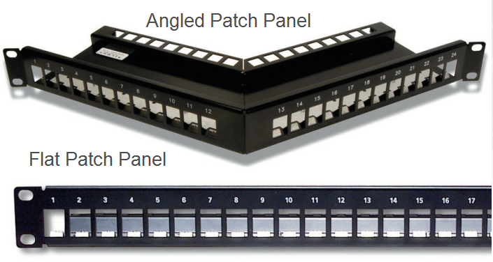
Flat vs. Angled Patch PanelOn the basis of the appearance design, the copper patch panel can be classified into flat and angled patch panel, as shown in the following figure. The flat patch panel enables the horizontal cabling and routes the cables into vertical cabling, while the angled patch panel makes the cable termination easy and patch cord routing improved. Compared with the former one, the angled design of the latter one increases the rack density, managing high-density applications in one-fourth the area needed for conventional cable management systems. But taking the front depth requirements of the angled patch panel into account, the angled patch panel is not so good for the cabinet installation as the flat patch panel.
As there are often 8 or 12-port configurations on the common patch panel, the high density patch panel is usually designed with 24 or 48 ports as an ideal solution for the applications where there is limited space. Since there are much more ports in the high density patch panel to connect and manage the incoming and outgoing Ethernet cables, it has the ability to conserve the rack space. Hence, if the space is limited in your network, then you can choose the high density patch panel to deploy your network cabling.
After discussion, it can be concluded that the unshielded patch panel is suitable for the applications where the EMI is not very high, while the shielded patch panel is more commonly used in the environments with high EMI. It can be also concluded that the flat patch panel is a good choice if you want to easily deploy the patch panel. Otherwise, the angled patch panel is highly suggested. Besides, if there is limited space in your network, you are recommendable to choose the high density patch panel rather than the common one for conserving space. For easier network deployment and better cabling management, you’d better pick the most suitable patch panel for your cabling network.
Posted by: katherinewangfs at
09:31 AM
| No Comments
| Add Comment
Post contains 888 words, total size 7 kb.
January 13, 2017
There is no denying that it is very convenient for the public to use the wireless network, which is more and more popularly used in recent years. However, if the high speed and efficiency are required, the wired network must be more suitable for you to choose, which always works with Ethernet patch cables to enable a more secure network with faster speed. In general, except for some special devices like cellphone that can only used in the wireless network, the rest of your devices will perform better in the wired network.
Would you also like to deploy a wired network for your home? Since the deployment of a wired network is more sophisticated than that of a wireless network, this paper will present some considerations for you to set up a fast and smooth wired home network.
Before deploying the wired network, there are some points that you should take into account. Firstly, you must decide how many rooms you want to run your wired network through, which will mainly determine the deploying budget. Because it will dictate how many feet of Ethernet patch cable you need to use. Secondly, you must confirm how many devices you would like to connect to the network and where you decide to locate them. Thirdly, since there may be a lot of Ethernet patch cables put in use in the wired network deployment, the wire distribution also becomes very crucial for a neat and smooth wired network which you should attach importance to. Considering that these Ethernet cables would be easy to mess up, you’d better to design the wired network and consider all possible problems that may occur during the installation.
Besides, there are two notes that you should also pay attention to when designing the network. The one is not to place the Ethernet patch cables near the devices, for instance, microwave and TV, which will have a negative effect on the performance of data transmission. Another one is to put the router in a central place of your network, ensuring good signals when your network runs.
As we all know, choosing a proper patch cable is extremely important that can make a great difference to the network speed. If you want to gain a stable network with high data transmission rate, then you should choose the most suitable cable for your network. At present, the patch cables used for the wired networks are usually Ethernet patch cables, which can be divided into various types, such as, Cat 5, Cat 5e, Cat 6, Cat 6a, Cat 7 patch cable, etc. Among these types, Cat 5e and Cat 6a patch cable are more commonly used the wired network in recent years, both of which are highly recommended as the cost effective solutions.
After making the decisions about where and how the cables will be distributed, you should firstly measure the distances of the connections in your network and calculate how long the Ethernet patch cable the whole connection needs, as the Ethernet patch cable is the main equipment in the network. To avoid some unexpected issues, the whole length of the Ethernet patch cable you prepare should slightly longer than the calculated length.In addition, there are many other tools you should also prepare before the installation, for example, wall plates, jack ports, drywall cutters, cable clips, etc. All these tools will be used in the installing process. Hence, you should check and confirm the preparation, so that the installation procedures will be smoothly processed as planed.
There is no doubt that the wired network performs higher than the wireless network, although the deployment of the wired network is much more sophisticated. If you want to own a more secure and faster network, then the wired network would be a better choice for you and the points mentioned above are three important factors that would be useful for you to make a fast deployment for the smooth wired home network.
Posted by: katherinewangfs at
09:02 AM
| No Comments
| Add Comment
Post contains 681 words, total size 5 kb.
January 11, 2017
The patch panel, also known as the patch bay, patch field or jack field, is a functional unit with a number of same or similar jacks, designed to conveniently and flexibly connect, disconnect and monitor circuits in the cabling network. There is no doubt that the patch panel plays an important role in collecting data and routing it to the intended destination, with the function of enabling the ease of cabling network management and avoiding the data transmission error or failure.
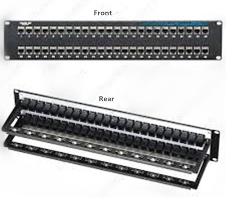
At present, there are both copper and fiber patch panels available on the market, both of which are very popularly used due to their features and advantages. To better know about the patch panel, here offers a kind of 48 port cat6 patch panel in the following figure. From this figure, you can easily learn the appearance of the front and rear of the 48 port cat6 patch panel.
We used to regard the patch panel as the "traffic light†for our cabling network. Is there any evidence to support this statement? In fact, we can’t deny that no matter how large or small the patch panel is, it is always the crucial element in our cabling network that has the ability to terminate cable elements and transmit the signal to the final destination. Moreover, using the patch panel can better install and manage the multiple cables in our cabling network, for an easier cabling management.
With the mentioned above advantages and constantly improved functions, the patch panel becomes more and more commonly used in computer networking, recording studios, radio, television, etc. Since it is so important to our system, we should ensure that there is no problem with the patch panel before our system runs. Because if there is something wrong with the patch panel, the data would be transmitted wrongly or unsuccessfully.
As the patch panel is so crucial in the administration of the telecommunications network, it is highly recommended to select a proper patch panel for better cabling management. Since there are both copper and fiber patch panel available on the market, let’s discuss the advantages and disadvantages of the two kinds of the patch panels and select one type which is the most suitable for our system.
It is well known that the patch panel can be part of networks with either fiber or copper cabling. As fiber can transmit the signals faster than copper, does it mean that fiber patch panel performs better than copper patch panel in the cabling network? The answer is no. Why? Because all the patch panels are subject to the same standards that provide signal and speed performance ratings for other network components, no matter which materials the patch panels are made up of. Meanwhile, the patch panel is primarily used for directing signal traffic rather than move signal at a required speed. Hence, the materials of the patch panels do make little difference in the cabling performance. As for the manufacturing cost, fiber patch panel is much expensive than copper patch panel that can be up to 40 percent higher. In short, copper patch panel is really a good choice for cabling network if the three factors mentioned above is considered.
Is there any advantage if we choose the fiber patch panel for our cabling network? Of course. The fiber patch panel has only two ports and doesn’t require the hardwiring, which is much easier to install than the copper patch panel. After all, each pair of the wires should have a port if you choose the copper patch panel, which may take more time to install.
The patch panel is the "traffic light†in cabling network which allows for terminating long and troublesome cables, enabling the signals to be transmitted directly through a patch code to its destination. Although there are both copper and fiber patch panel available on the market, the copper patch panel is highly recommended as an cost effective solution. Do you consider owning one copper patch panel at hand? You can simply get it from FS.COM that offers 24 port cat5 patch panel, 48 port cat5 patch panel, 24 port cat6 patch panel and 48 port cat6 patch panel.
Posted by: katherinewangfs at
08:28 AM
| No Comments
| Add Comment
Post contains 722 words, total size 5 kb.
January 06, 2017
Although the copper-based patch cable performs not so well as the fiber patch cable in Ethernet network, it is still popularly used due to its advantages of low cost, high flexibility, easy installation and operation. So far, there are various kinds of copper-based patch cables that were published and came into the market in succession, such as, cat5/cat5e, cat6/cat6a and cat7 Ethernet cable, etc. Among these copper-based patch cables, Cat5e and Cat6 Ethernet cable are two of the most commonly applied types that have similar features and functions, which may be a little hard to distinguish. Do you also feel confused? Let’s study the knowledge of these two patch cables and acquire which one is more suitable and cost effective to be used.
Cat5e Ethernet cable is an improved version of Cat5 Ethernet cable, published in early 2001. In comparison with Cat5 Ethernet cable, it has a very similar appearance, but composed of four pairs of copper wires rather than the two pairs that cat5 Ethernet cable features. Furthermore, the pairs of copper wires in the Cat5e Ethernet cable are twisted more tightly, reducing or eliminating the crosstalk when working in Ethernet network. After the upgrades, it has become the most common type of Ethernet cabling applied in modern homes and offices, offering much faster transmission rate, wider bandwidth and higher performance. From the following figure, you can see a blue Ethernet cable on the left side which is just an example of the Cat5e Ethernet cable.
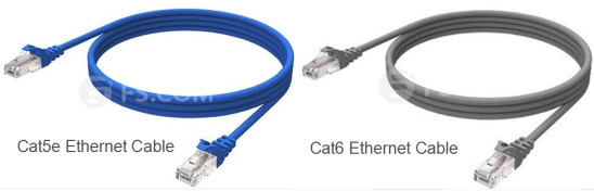
The one on the right side of the figure is a Cat6 Ethernet cable, which was introduced to the market a year later than the Cat5 Ethernet cable. It is usually made up of four unshielded twisted pairs (UTP) and terminated with RJ45 jacks, capable of supporting the 10Base-T (Ethernet), 100Base-TX (Fast Ethernet), 1000Base-T (Gigabit Ethernet) and 10GBase-T networks. Compared to the Cat5 Ethernet cable, the Cat6 Ethernet cable increases the frequency responses, tightens the crosstalk specifications and introduces more comprehensive crosstalk specifications, for a greatly enhanced performance.
After knowing the basic information of cat5e and cat6 Ethernet cable, you must recognize that these two Ethernet cables feature different characteristics and perform differently, even if they seem to have common in appearance and function. Then what’s the detailed information about the differences between cat5e and cat6 Ethernet cable?
Different Transmission SpeedThere is no doubt that the transmission speed is always the priority if you are considering making the upgrades for your Ethernet network, so does the upgrades from cat5e to cat6 Ethernet cable. As the cat5e Ethernet cable is able to used in 1GBase-T network at most and can only performs up to 100 MHz, the cat6 Ethernet cable is improved to support 10GBase-T network with data rate of up to 250 MHz that is more than twice that of the cat5e Ethernet cable.
Different Transmission DistanceAs we all know, cat5e and cat6 Ethernet cable are copper-based patch cables which are only able to transmit signals for very short distances. What’s more, the data rate also affects the transmission distance. In simple words, the higher the data rate is, the shorter the transmission distance will be. Hence, when the signals are only need to be transmitted in a low data rate, both cat5e and cat6 Ethernet cable have the ability to transmit them at lengths up to 100 meters. But if the data rate is required to be the maximum speed, the cat5e and cat6 Ethernet cable can only reach 37 meters and 50 meters, separately. If transmission distance is longer than 100 meters, you are suggested to use the repeaters or switches to amplify the signals.
Different ReliabilityThe network reliability is also an important factor that you should take into account when deploying your network. Because if there are serious electrical interference in your network, the network reliability may be not so good and negatively influence the performance of your network, thereby the data transmission in your network would be in a wrong way or failed. To ensure a more reliable and stable network, the reliability upgrades is also done from cat5e to cat6 Ethernet cable, with the improvement of deterring signal interference from affecting your network. By using the advanced cat6 Ethernet cable, you’ll be able to have a longer and more reliable period of uptime, regardless of how close your network is to other surrounding networks.
The upgrades always occur with improved features swiftly, like the copper cable upgrades, to face the increasing requirements of the Ethernet network. Since the cat6 Ethernet cable is designed with the improved features of faster transmission speed, longer transmission distance and higher reliability, it is much more commonly used than cat5e Ethernet cable that can be available at a little expensive cost. Hence, you are strongly recommended to use cat6 Ethernet cable to deploy your network with higher performance.
Posted by: katherinewangfs at
10:21 AM
| No Comments
| Add Comment
Post contains 828 words, total size 6 kb.
January 04, 2017
It is well known that network patch cable can be commonly wired as straight-through or crossover cable, used for data transmission. Both of these two network patch cables are made up of four pairs of high performance twisted wires with different colors, terminated by the RJ45 keystone jacks at each side of the cables. As for their applications, they are designed for serving different aims, with different wire arrangements inside their cables, which will be introduced in the following text for guiding you to pick the most proper one for deploying you network.
Before discussing the differences between the straight-through and crossover cable, it is necessary to introduce two wiring standards, T568A and T568B, for better understanding the different wire arrangements in each kind of the cable. These two kinds of wiring standards are recognized by ANSI, TIA and EIA for wiring the network patch cables. Generally, the T568B wiring standard is more widely used than the T568A wiring standard, as the default wiring scheme for twisted pair structured cabling. If you are unsure of which to use, then choose T568B to arrange the wires inside the cable.
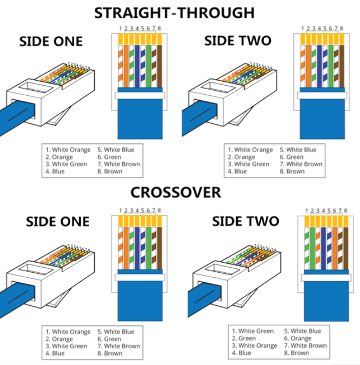
In general, there are eight colored wires in a straight-through or crossover cable, which should be arranged according to the corresponding order of the wiring standard T568A or T568B. That’s to say, the wires with different colors should be terminated in the right positions of the RJ45 keystone jack where the wire colors and the colors in the RJ45 keystone jack are the same, as shown in the figure above.
When choosing the network patch cable in the store, you’ll easily find the straight-through cable that is commonly used to connect computers to hubs or switches. While the crossover cable with the function of connecting a computer to another computer should be a little hard to find since this kind of network patch cable are not so commonly used as the previous one. But what are the differences between the straight-through and crossover cable? Let’s talk about this topic.
Different Wire ArrangementsAs mentioned above, these two kinds of network patch cables have different wire arrangements. For a straight-through cable, there should be only one wiring standard used. It means that both ends of one straight-through cable can be only wired according to T568A wiring standard or T568B wiring standard. Since T568B wiring standard is more popular, here offers the example of a straight-through cable with T568B wiring standard in the following figure. As for the crossover cable, it is designed with two wiring standards in both ends of the cable. In simple words, if there is a RJ54 keystone jack with T568A wiring standard in one end of the crossover cable, there must be a RJ54 keystone jack with T568B wiring standard in the opposite end, as shown in the following figure.
The two kinds of network patch cables are available in the market, used for different applications. As for the straight-through cable, it is applied in local area networks to connect different kinds of devices, for instance, connect a computer to a switch/hub's normal port or a cable/DSL modem's LAN port. It can be an alternative to wireless connections where one or more computers access a router through a wireless signal. As for the crossover cable, it's usually used to connect same type of devices, such as, connect two computers directly, connect two switches/hubs by using normal port in both switches/hubs.
After discussion, we can concluded that the straight-through and crossover cable are designed with different arrangements, serving for different applications. The straight-through cable is usually used for connecting two different kinds of devices, while the crossover cable is highly recommended in the applications where same kind of devices need to be connected. If you want to distinguish the two kinds of cables, you can just check the color orders for the wires inside the RJ45 keystone jacks at both ends of the cables. If the color orders of the wires are the same on both ends, it means the network patch cable is a straight-through cable. If not, it must be a crossover cable or there may be a wiring error in the cable.
Posted by: katherinewangfs at
08:37 AM
| No Comments
| Add Comment
Post contains 714 words, total size 6 kb.
December 29, 2016
Are the Ethernet patch cables you purchase from the local or online stores always at the proper length? Or not so suitable for your network because they are too long or too short that don’t meet your expectations? Have you ever considered making the improper Ethernet patch cable into a suitable one by yourself, so that you can deploy your network by using you own Ethernet patch cable and save a lot of money, time and space? In fact, terminating the Ethernet patch cables is not so difficult but very useful for fast network deployment, which will be presented in the post. Meanwhile, there are several important things you should take into consideration before making the Ethernet patch cable termination, which will be also illustrated in details. Hope these information will guide you to make your own Ethernet patch cable and then deploy your Ethernet network in a very fast, smooth and cost effective manner.
Before making the Ethernet patch cable termination, you should choose one kind of Ethernet patch cable which is most suitable for your network, since there are various kinds of Ethernet patch cables available on the market, such as, cat5, cat5e, cat6, cat6a, cat7, etc. Considering that cat5e, cat6 and cat7 patch cable are the most commonly used ones at present, both of which will be introduced the following text.
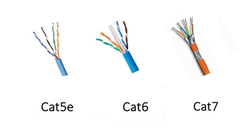
As an upgrade version of cat5 patch cable, cat5e patch cable has the ability to support gigabit speed, allowing for a faster, more reliable and steady network. It is much commonly used in home and office applications. As for cat6 patch cable, it is an enhanced version of cat5e patch cable that has much more sophisticated structure, as shown in the above figure. It is an ideal solution to face future-proof network that supports the transmission speed up to 10 gigabit with a long transmission distance. In contrast to cat5e and cat6 patch cable, cat7 patch cable is a kind of shielded Ethernet cable that has a great improvement in the capacity and reliability. It is more expensive since it has been the most durable and longer-lifespan Ethernet patch cable at present. As for the structural differences among cat5e, cat6 and cat7 patch cable, it is very easy to learn from the above figure.
In general, there are two common wiring schemes, T568A and T568B, which are designed to specify the arrangement of the colored wires for terminating the Ethernet patch cable. That’s to say, if you want to terminate your cable, you should arrange the colored wires in a correct order according to the standard of T568A or T568B, as shown in the following figure. As for their applications, T568A is always applied in home-networking connections, while T568B is strongly suggested for the preexisting residential network wiring or other similar projects.
There are ten detailed steps to make the Ethernet patch cable you need at an exact length, which will be presented below. Terminating the cable you need according to the following step-by- step procedures can ensure the performance of the DIY cable and the stability of your network.
- Prepare the essential tools and materials for the cable termination, including some RJ45 connectors, a pair of wire scissors or wire strippers, a spool of Ethernet cable, a RJ45 crimping tool and a network cable tester.
- Use the wire scissors or wire strippers to cut the Ethernet patch cable you need into a desirable one with the exact length. Besides, you’d better to add two or three inches extra no matter how long you want the Ethernet patch cable to be, for the sake of messing up.
- Utilize the RJ45 crimping tool to shove the sheath of the cable (about 1 inch) from the end of the cable into the stripper, and lightly squeeze the crimping tool.
- When the razors slice of the crimping tool pass through the cable jacket, you should twist the cable and pop off the cut end of jacket.
- Once the jacket is stripped, you can see four twisted pairs of wires with four different colors. You should separate these four pairs of wires into eight individual wires and rearrange them into sequence according to the color order in T568A or T568B.
- Cut the tips of the wires in order to match with the RJ45 connector. Then guide the wires into the plug and slip them into their own channels. The ends of the wires should reach as far as possible toward the front edge of the plug.
- Double check and confirm whether the wires are in sequence according to the right order or not, avoiding error connection.
- Insert the plug into the crimping slot of the crimping tool and squeeze the crimping tool to make the pins inside the plug into the wires and fasten the plug onto the cable. Hence, the RJ45 connector can be a permanent part of the new cable.
- As for the other end of the cable, just terminate it in the same way, so that you can finish the whole termination process for your own Ethernet patch cable.
- Test the cable by a network cable tester to confirm that it really works. In addition, if it doesn’t work, you are highly suggested to check the color order of the wires first.
Before making your own Ethernet patch cable, you should choose a proper Ethernet patch cable and a wiring scheme according to your network requires. As for the process of making the cable with an exact length, it is not so difficult as you consider, but easy and fast. The only thing that deserves a bit of attention is to be careful in the whole termination process, so that the Ethernet patch cable can be made at a proper length and work with your network like a charm.
Posted by: katherinewangfs at
08:15 AM
| No Comments
| Add Comment
Post contains 992 words, total size 7 kb.
December 23, 2016
As we all know, fiber optic cable jumper plays an important role in Ethernet network connection, which becomes more and more diversified to satisfy the different connection requirements in recent years. For instance, standard fiber patch cable like single mode patch cable and multimode patch cable, special fiber patch cable like mode conditioning patch cable and bend insensitive patch cable, etc. Among these various fiber patch cables, mode conditioning patch cable has been one of the most popularly used fiber patch cable due to its unique features and advantages, which will be introduced in the following text.
Mode conditioning patch cable is a special kind of duplex fiber patch cable that consists of two fibers, a conditioned fiber and a non-conditioned fiber, capped at either end with connectors. In the conditioned fiber, a single mode fiber and a multimode fiber are fusion spliced in an offset manner, with a precise core alignment and angle, protected by a black over-wrap. While in the non-conditioned fiber, there is only a length of multimode fiber. To get a better understand of its structure, you can take the following figure as reference.
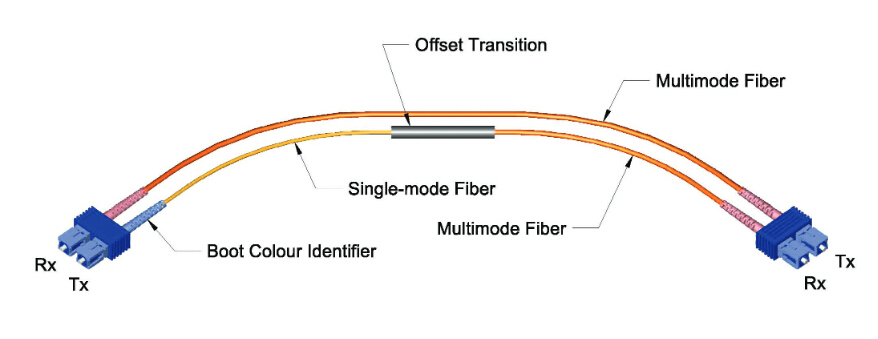
As shown in the figure above, there are two multimode fibers in one end, and a multimode and single mode fiber in the opposite end. The end with two multimode fibers is designed to connect the cable plant, while the other end connects to the transceiver equipment with the single-mode leg linking to the transmit side. Hence, light signal can be launched on to the multimode fiber in the conditioned one at a specific angle, giving the patch cable its mode conditioning property. Besides, it is worth mentioning that this kind of fiber optic cable is fully compliant with IEEE 802.3z application standards.
As far as our information goes, 1310nm long wave signal is always transmitted through single mode patch cable for 1000BASE-LX transmission as a cost effective solution. However, if the mentioned above transmission utilizes multimode patch cable, it will cause a phenomenon known as DMD (differential mode delay). In simple words, if the same signal is carried to a multimode patch cable, there will be multiple signals created in the multimode patch cable that may make transmission errors to some extent.
In order to solve this problem, mode conditioning patch cable is put forward that utilizes an offset between the single-mode fiber and multimode fiber to eliminate transmission errors, allowing for 1000BASE-LX signal transmission through multimode patch cable. For example, when 1000BASE-LX routers and switches are installed into existing multimode cable plants, mode conditioning patch cable is highly recommended to adapt the single-mode output of 1000BASE-LX transceivers to a multimode cable network.
After knowing the feature and advantage of mode conditioning patch cable, do you also consider using mode conditioning patch cable to finish the conversion from single mode to multimode? Here are some notices for you so as to use the mode conditioning patch cable in a proper way.
-
Mode conditioning patch cable should be used in pairs to finish the conversion. That’s to say, most orders for this kind of fiber optic cable are always in even numbers. If there is an odd number order, the single one must be used for standby application or replacement.
-
Mode conditioning patch cable is only able to convert single-mode transmission to multimode transmission. If the conversion from multimode to single-mode is required, you are suggested to choose a media converter as an easy and cost effective solution.
-
Please check and confirm the connector of your switch before application. If it is equipped with SC or LC connectors, you should connect the yellow leg (single-mode) of the cable to the transmit side and the orange leg (multimode) to the receive side of the equipment. It is imperative that this configuration should be maintained on both ends.
Mode conditioning patch cable enables the conversion from single-mode to multimode with the feature of fusion splicing between single mode fiber and multimode fiber. After knowing its feature and advantage, if you want to choose this kind of cable to finish the conversion in your network, you can order it from FS.COM. It is no doubt that there are various mode conditioning patch cables with different connectors available. Besides, if you cannot find one to meet you requirement, you can also order custom fiber patch cables for your network.
Posted by: katherinewangfs at
01:50 AM
| No Comments
| Add Comment
Post contains 752 words, total size 6 kb.
December 16, 2016
As we know, duplex LC interfaces are widely used in 10G SFP modules, for instance, SFP-10G-LR-S module and SFP-10G-SR module, which occupy the majority of 10G module market. However, for 40G QSFP+ modules, both LC interface and MTP/MPO interface play important roles in meeting the high speed transmission, which are available on 40G QSFP module market. What are the differences between these two interface types? Which one should be chosen when deploying 40G Ethernet network? Do they function similarly in the same application? Let’s talk about this topics and find one kind of 40G QSFP+ module with the most suitable interface type so as to make a smooth 40G connection for our network.
From the following figure, we can see the examples of QSFP+ modules with two different interfaces. The left one is the module with with LC interface, while the right one is with MTP/MPO interface. The differences between these two kinds of modules vary from the fiber types they work with to the working principles, which will be analyzed in the following text.
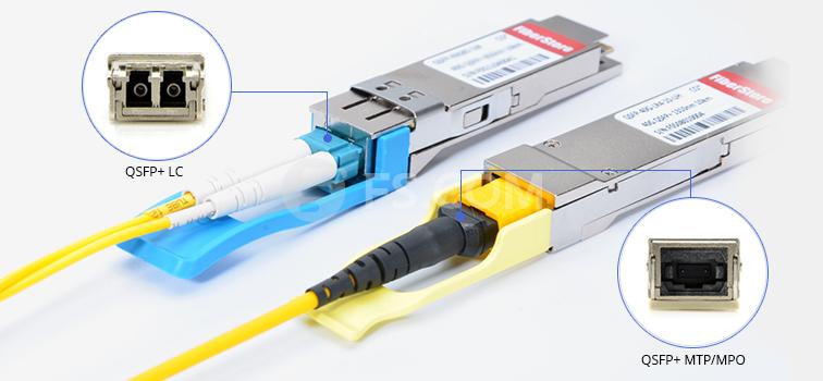
As for the QSFP+ module designed with LC interface, it usually works with single mode fiber (SMF). Since SMF is able to support 40G network for a very long distance, the LC interface module is widely applied in long transmission. However, the QSFP+ module with MTP/MPO interface design is strongly recommended in the short distance application where the 40G signals are transmitted through multimode fiber (MMF). What should be paid attention to are some special QSFP+ modules, like QSFP-40G-PLRL4 and QSFP-40G-PLR4 module, which don’t fit the rule. Although the two kinds of modules mentioned above are designed with MTP/MPO interfaces, they are also capable of supporting 40G long distance transmission through SMF.
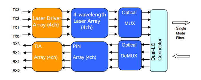
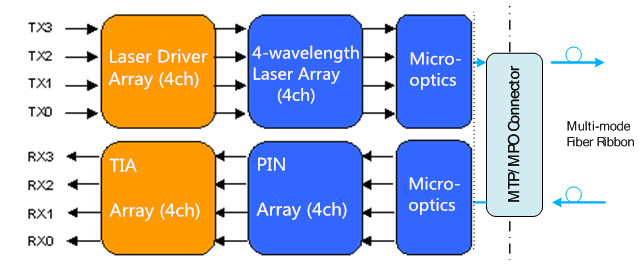
As shown in the following figure, QSFP+ module with LC interface has a very complicated working principle for transmitting 40G signals. At the beginning of the transmission, four 10G serial data signals via four channels are transmitted to laser drivers in the transmitting side. Then they are directly controlled by the laser drivers as four modulated lasers (DML) with different wavelengths. After that, the output of four DMLs are optically multiplexed as a total 40G optical signal and transmitted through the LC connector and the SMF. While in its receiving side, the 40G optical signal is demultiplexed into four individual 10G signals with different wavelengths, then collected by the discrete photo diode, and finally amplified by the TIA and outputted as electric data.
As for QSFP+ module with MTP/MPO interface, its working principle is much easier than the previous one as it doesn’t require CWDM technology. In its working process, the transmitter firstly converts four 10G parallel electrical input signals into parallel optical signals by using the laser array. Then the four 10G parallel optical signals are directly transmitted through the MMF ribbon in a parallel mode. Finally, these parallel optical signals are transmitted through the photo detector array and converted into parallel electrical output signals in the receiving side. To better understand the working principle, here offers the figure of its detailed working process.
Besides, the mentioned above QSFP+ module with MTP/MPO interface, like QSFP-40G-PLRL4 and QSFP-40G-PLR4, also works in a parallel mode that features four independent transmitting and receiving channels to finish 10G operations, achieving a whole 40G connection. The only difference of the working principle is that the signals are transmitted and received through eight SMF ribbons, hence this kind of module can also achieve a long distance transmission.
From this article, we can easily find that QSFP+ module with LC interface is more commonly used for long distance application, while QSFP+ module with MTP/MPO interface is a cost effective solution for short distance application. Except that, there is still a great difference for applications between the two kinds of modules due to their different working principle. As QSFP+ module with LC interface uses CWDM technology to transmit signals with different wavelengths through a pair of single mode fibers, the 40G signals can’t be separated into four 10G signals and transmitted to 10G devices. However, QSFP+ module with MTP/MPO interface can be used in the 40G to 10G application by using an external 12-fiber parallel to 2-fiber duplex breakout cable.
Posted by: katherinewangfs at
09:32 AM
| No Comments
| Add Comment
Post contains 723 words, total size 6 kb.
December 14, 2016
With the continuously growing demand for higher capacity and bandwidth, the deployment of 40G Ethernet network becomes much more necessary than ever before. As one of the key components to accomplish a whole 40G connection, QSFP+ transceiver, a compact, hot-pluggable module, is designed with four independent channels to transmit and receive 10G signals, supporting 4x10 Gbit/s data rates. This kind of module can be used both in 40G to 40G application where one QSFP+ transceiver will be connected to another QSFP+ transceiver and in 10G to 40G application where one QSFP+ transceiver will be connected to four SFP+ transceivers.
Do you also want to upgrade your system from 10G to 40G Ethernet network by using QSFP+ transceiver? The following will detailedly describe the step-by-step procedures for installing QSFP+ transceiver and attaching optical network cable to the transceiver, which will be helpful for you to achieve a fast, smooth and seamless 40G network deployment.
Before installing QSFP+ transceiver, three tools should be prepared for the 40G migration. One is the wrist strap or other grounding device with the function of avoiding ESD (electro-static discharge) occurrence. Another is the antistatic mat or antistatic foam, capable of setting the transceiver on. The other is the equipment for fiber-optic end-face cleaning and inspection. All of these tools are indispensable for making a secure and smooth installation.
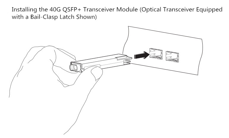
After that, you can start to install the QSFP+ transceiver according to the following procedures. Considering that there is either a pull-tab latch or a bail-clasp latch in QSFP+ transceiver, the procedures for both types will be listed below.
- Put the ESD wrist strap on and attach the other end of the ESD wrist strap to a properly grounded point on the chassis or the rack.
- Get the QSFP+ transceiver by removing its protective packaging.
- Check the QSFP+ transceiver label and confirm whether the type of the module is suitable for your network or not.
- Remove the optical bore dust plug from the transceiver and store it in a clean place, therefore it can be easily found and fast used next time.
- Since there are two kinds of latches for the transceivers, they should be connected to your network in different ways. As for the transceiver with a pull-tab latch, you should hold it to ensure the identifier label is on the top. As for another transceiver, you should keep its bail-clasp aligned in a vertical position (see the following figure).
- Then align and slide the transceiver to the module socket carefully until it contact with the socket electrical connector.
- Press firmly on the front of the QSFP+ transceiver with your thumb to fully seat the transceiver in the module socket.
- Reinstall the dust plug into the transceiver optical bore before attaching the optical network cable to the transceiver.
After installing the QSFP+ transceiver, you should attach the optical network cable to the transceiver to finish the whole 40G transmission. But how to attach the optical network cable? What should be paid attention to in the attaching procedures? The following will talk about this topic and give you answers.
Before making the 40G connection, you should ensure that the unplugged optical network cable connectors and the transceiver optical bore are protected by the dust plugs. Meanwhile, you should also check and clean the MPO connector or duplex LC connector end faces. Besides, you can only grasp the connector housing to plug or unplug the optical network cable. Once these points are confirmed, you can attach the optical network cable to your network.
The procedures for attaching the optical network cable to the transceiver are shown below.
- Remove the dust plugs from the optical network interface cable connectors and the QSFP+ transceiver module optical bores. Also, keep the dust plugs in a clean place.
- Check and clean the connector end faces of the optical network interface cable.
- Immediately attach the optical network interface cable connector to the QSFP+ transceiver.
- Pull slightly on the cable connector boot to check whether the optical network cable is fully seated. If not, please reattach it and make it seated.
From this paper, it can be easily learned to install the 40G QSFP+ transceivers and attach the optical network cables to the QSFP+ transceivers, hence the 40G connection can be smoothly finished in a correct way. Using the methods mentioned above to upgrading your network can protect the QSFP+ transceivers from being damaged and keep a stable performance for the 40G connection.
Posted by: katherinewangfs at
10:18 AM
| No Comments
| Add Comment
Post contains 755 words, total size 6 kb.
December 09, 2016
Nowadays, there is a widespread concern over the migration from traditional 10G to 40/100G Ethernet network, which seems to be an irreversible trend. As we know, 40/100G Ethernet network can greatly address the problem of very low network speed. Do you also consider upgrading your system for higher bandwidth and larger capacity? There is no doubt that fiber cables must be the first choice for a smooth 40/100G migration, which almost makes copper cables obsolete. But which kind of fiber should be chosen? Is there any key notice should be taken into consideration when selecting fiber for the migration? These problems will be explored and answered in the following parts.
It is reported that over 80% of data centers support their network within 100 meters in recent years. That’s to say, if the fiber has the ability to transmit 40/100G signal for a short distance, it almost satisfies the needs for migration. In general, there are single mode and multimode fiber available for data centers, both of which are capable of supporting 40/100G data transmission links. But which one is the most cost effective for a whole 40/100G system? Let’s talk about it and seek the answer.
For single mode fiber, it can only carry a single light signal and has little modal dispersion in the transmission process, which is highly recommended for long distance transmission. While for multimode fiber, it is able to carry several light signals in the different modes that results in serious dispersion. What’s more, the longer the signals are transmitted, the larger the dispersion will be. Hence, multimode fiber is more popularly used in short distance transmission and much more inexpensive than single mode fiber.
In short, although single mode fiber has a higher performance in data transmission, multimode fiber is more suitable for 40/100G migration as the most cost effective fiber solution.
There are two kinds of multimode fiber patch cables, OM3 patch cable and OM4 patch cable that allow for smooth 40/100G migrations with different transmission distances. The following figure shows some commonly used transmission cases in 10G, 40G and 100G network, both of which are able to use short--wavelength (850 nanometer) transmission over OM3 and OM4 patch cable.
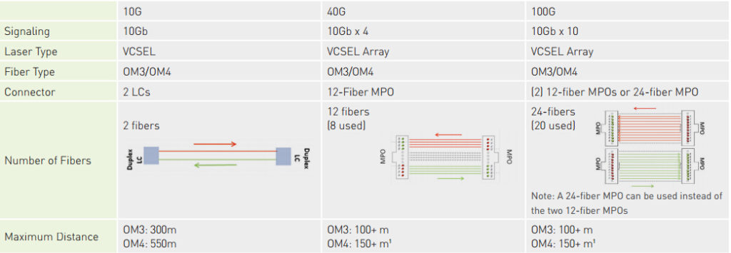
From the figure, we can easily learn that both OM3 and OM4 patch cable are suitable for 10G, 40G and 100G applications. As for OM3 patch cable, it is able to support 10G network at lengths up to 300 meters and 40/100G network at lengths up to 100 meters. Compared to OM3 patch cable, OM4 patch cable can transmit signals longer under the same network, which is also a little bit expensive. In fact, its transmission distance can be 550 meters in 10G network and 150 meters in 40/100G network.
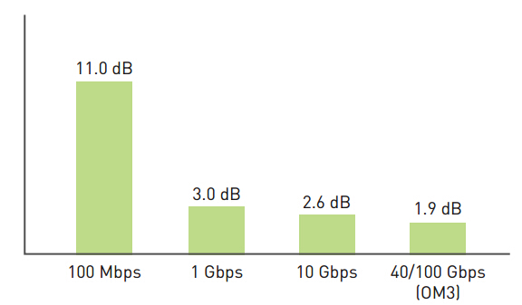
It is obvious that different cables have different channel insertion loss in 40/100G network, which may have different influences on the signal transmissions. Once the channel insertion loss is high, it may cause a failed or wrong signal transmission. So that, the channel insertion loss should be also noticed when selecting fibers.
As shown in the following figure, the channel insertion loss by using OM3 patch cable is about 1.9 dB in supporting 40/100G data transmission link which is much lower than in supporting 10G link. If OM4 patch cable is selected to transmit 40/100G signals, the channel insertion loss is only 1.5dB. Undoubtedly, OM4 patch cable performs better than OM3 patch cable in this aspect.
Are you ready to make the 40/100G migration? If yes, you are suggested to choose multimode fiber as the most cost efficient fiber solution. According to the data transmission distance, you can choose OM3 patch cable to support 40/100G link at length up to 100 meters, which is more inexpensive than OM4 patch cable. If the distance can’t meet your requirement, you are suggest to choose OM4 patch cable with lower channel insertion loss.
Posted by: katherinewangfs at
09:58 AM
| No Comments
| Add Comment
Post contains 673 words, total size 5 kb.
December 08, 2016
To face the challenge of migration from 10G to 40/100G Ethernet network, the fiber technology for higher data transmission speed has developed in a really fast manner. Under this trend, a series of high density fiber equipment, especially MPO/MTP products, are designed to control the costs, by way of maximizing return on assets. Have you ever known about MPO/MTP products, for instance, MPO/MTP cable, MPO/MTP cassette and MPO/MTP patch panel, which are very popularly used in recently years? Among these high density products, MPO/MTP cassette plays an indispensable role in 10G to 40/100G migration, as one of the ideal solutions for high density data centers. The following will mainly introduce the basic information of MPO/MTP cassette and illustrate how it is used for 10G network and the upgrading from 10G to 40/100G network.
MPO/MTP cassette is a modular module that offers secure and smooth transition between MPO/MTP and LC or SC discrete connectors, achieving a better management on the high density fiber cabling system. It is always loaded with 12 or 24 fibers, with LC or SC adapters on the front side and MPO/MTP adapters at the rear, which enables user to take the fibers brought by a trunk cable and distribute them to duplex cable.
At present, there are two types of MPO/MTP cassettes available, LGX MPO/MTP cassette and HD MPO/MTP cassette, both of which have the advantage of scalability to increase density for optimum serviceability and manageability if the data center requires. Besides, there is a special kind of cassette designed with TAP port, which can be used to easily access and monitor the data.
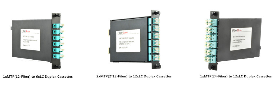
As we all know, the most widely used interface of 10G optics is LC connector. Accordingly, the commonly used MPO/MTP cassettes are MTP-LC cassettes that feature optimized performance and superior optical and mechanical properties. The following figure will show three MTP-LC cassettes, 1xMTP(12-Fiber) to 6xLC duplex cassette, 2xMTP(2*12-Fiber) to 12xLC duplex cassette and 1xMTP(24-Fiber) to 12xLC duplex cassette, with specific port configurations. Both of them can be used for 10G network and the application from 10G to 40/100G.
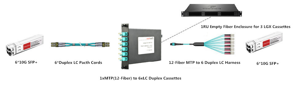
MPO/MTP cassette can be used for 10G network, with the function of connecting one 10G device to another one. It is generally known that a duplex LC fiber patch cable can be chosen for direct connection if the two 10G devices only need to be connected for a short distance transmission. However, once long distance transmission is required between the two devices, a MPO/MTP cassette would be a good choice for this 10G interconnection or cross connection. In the following figure, it gives an example of a 1xMTP(12-Fiber) to 6xLC duplex cassette used for 10G long distance transmission.
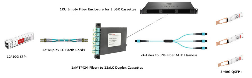
It is highly suggested to use a MPO/MTP cassette to connect 10G device to 40G device, as an optimal solution. Similarly, if the distance is very short between the 10G device and the 40G device, a MTP-4 duplex LC fiber patch cable can be used for direct connection. But when long distance connection is needed, this method can’t meet the requirement any more and a MPO/MTP cassette is strongly recommended for this interconnection or cross connection. The following figure also presents an example of 1xMTP(24-Fiber) to 12xLC duplex cassette for 10G to 40G connection.
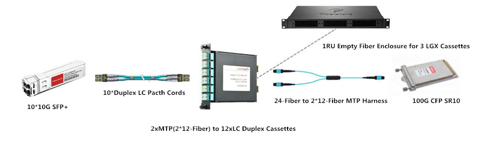
From the following figure, we can learn a 2xMTP(2*12-Fiber) to 12xLC duplex cassette is used for the 10G to 100G application. Is there any point we should note in the upgrading? Of course, a MTP-10 duplex LC fiber patch cable can simply address the upgrading for direct connection if the 10G device is not far from the 100G device. But when the distance between the devices is very long, the MPO/MTP cassette is also very essential for the 10G to 100G application.
MPO/MTP cassette enables fast deployment of high density data center infrastructure that also allows for improved troubleshooting and reconfiguration during moves, adds and changes. At present, there are three most commonly MPO/MTP cassettes, 1xMTP(12-Fiber) to 6xLC duplex cassette, 2xMTP(2*12-Fiber) to 12xLC duplex cassette and 1xMTP(24-Fiber) to 12xLC duplex cassette, both of which are able to support 10G network and the upgrading from 10G to 40/100G.
Posted by: katherinewangfs at
02:37 AM
| No Comments
| Add Comment
Post contains 728 words, total size 6 kb.
December 01, 2016
It is well known that SFP+ transceivers like SFP-10G-SR and SFP-10G-SR-S are very commonly used and perform greatly in 10G short distance transmission. When higher bandwidth is required, several SFP+ transceivers can be used together to offer multiple 10G links as a common solution. However, if an individual 40G link is implemented in this case, it has the ability to perform higher with much faster data transmission rate than multiple 10G links. As the deployment of 40G Ethernet network is not so simple as that of 10G Ethernet network, the following will introduce three widely applied solutions for short distance transmission in 40G Ethernet network which can be useful for you to deploy individual 40G link instead of multiple 10G links.
With the popularity of 40G Ethernet network, 40G solutions, especially 40G QSFP+ modules, have been widely applied to finish 40G data transmission. At present, there are various kinds of 40G solutions available on the market, which are designed to support different applications. For 40G short distance application, three widely applied solutions, QSFP-40G-SR4, QSFP-40G-CSR4 and 40GBASE-CR4 QSFP+ direct attach copper cable will be introduced in details.
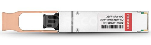
QSFP-40G-SR4 module is one of the most popular fiber optic transceiver for 40G short distances transmission, designed with 40GBase-SR4 standards. It is able to support high-bandwidth 40G signal transmission through 12-fiber parallel fiber, which is always terminated with MPO/MTP multi-fiber connectors. How long can it transmit 40G signals? If it works with OM3, it can support the 40G link at lengths up to 100 meters. If it transmit the 40G signals through OM4, the distance can be longer, 150 meters. In addition, QSFP-40G-SR4 module has the ability to connect four SFP-10G-SR modules by an 8-fiber MTP to 4 duplex LC cable. The following is an example of this module working with OM4 that you can find at FS.COM.
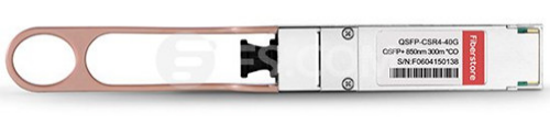
As for QSFP-40G-CSR4 module, it is always referred to as an upgraded version of QSFP-40G-SR4 module that has a better performance to support 40G short distance transmission. Its working principle is similar to the previous one, which also works through 12-fiber parallel cables with MPO/MTP connectors to support 40G optical link. Besides, connection with four 10GBase-SR interfaces still can be done in a parallel 4x10G mode by using duplex fiber breakout cables. What higher performance does QSFP-40G-SR4 module have? In fact, it is reflected on the transmission distance which is extended to 300 meters through OM3 and 400 meters over OM4. Here offers an example of QSFP-40G-CSR4 module that works with OM3 for your reference.
40GBASE-CR4 QSFP+ DAC can be also called 40GBASE-CR4 QSFP+ cable, which is very different from the first two 40G solutions. It is a pre-terminated copper cable with both ends terminated with QSFP+ modules. As for its working principle, it uses four lanes of twinaxial cable delivering serialized data at a rate of 10.3125 Gbit/s per lane to finish the 40G signal transmission.
Compared to the above-mentioned 40G modules, 40GBASE-CR4 QSFP+ DAC has a much lower manufacturing cost which is always not considered as a real optics, because of no expensive lasers or electronic components. At the same time, the transmission distance is also much shorter limited by the property of copper cable. In fact, it can only support the 40G signal transmission with a reach of 7 meters. Here also lists an example of 40GBASE-CR4 QSFP+ DAC for you to get a better understanding of the differences between this one and the above-mentioned modules.
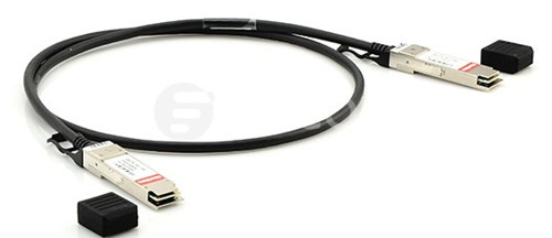
If the 10G Ethernet network can not meet your demands any more, you are suggested to deploy 40G Ethernet network for much higher bandwidth and faster data transmission rate. As for the 40G solutions for short distance transmission, you can choose it according to the transmission distance your network requires. In general, 40GBASE-CR4 QSFP+ DAC would be a good choice to support your system within 7 meters with the lowest price, while QSFP-40G-SR4 module is much more suitable to be used in the application within 150 meters. As for QSFP-40G-CSR4 module, it is the most expensive but optimal solution that has the ability to support 40G signal transmission at lengths up to 400 meters.
Posted by: katherinewangfs at
10:21 AM
| No Comments
| Add Comment
Post contains 715 words, total size 6 kb.
November 29, 2016
Since data centers have been experiencing an great infrastructure change to achieve higher levels of performance and scalability, the demand for 100G Ethernet network increases day by day. To better accommodate this great change, there are several kinds of transceivers designed for deploying 100G Ethernet network, such as, CFP, CFP2, CFP4, QSFP28, CPAK, etc. Among these 100G optics, QSFP28 transceiver offers the optimal solution for the 100G migration with the lowest power consumption which is very commonly used at present. In this paper, it will introduce QSFP28 transceiver and analyze the reason why QSFP28 transceiver is so popular in 100G Ethernet network.
As the smallest 100G form factor transceiver, QSFP28 transceiver has the same size and lane number as 40G QSFP+ transceiver, which is implemented with four 25-Gbps lanes to achieve 100G transmission. With the design of an upgraded electrical interface, it is able to support signals rates up to 28 Gbit/s that makes the deployment of 100G Ethernet network as easy as that of 10G Ethernet networks.
Generally, there are two types of QSFP28 transceivers, QSFP28 SR4 and QSFP28 LR4, which are used for different applications. As for QSFP28 SR4, it is suitable for 100G short distance transmission through multimode fiber up to 100 m. As for QSFP28 LR4, it is widely applied in 100G long distance transmission through single mode fiber, at lengths up to 10 km. The following figure shows the two types of QSFP28 transceivers for your reference.
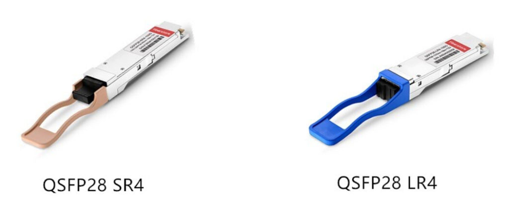
There is no doubt that QSFP28 transceiver has a lot of advantages that make itself more popular than other 100G optics. In order to better deploy 100G Ethernet network, QSFP28 transceiver is designed with a strong improvement that increases port density and decreases power consumption with a lower cost, which will be illustrated detailedly in the following text.
Higher Port Density: As we know, the first generation of 100G transceiver is CFP, which is designed with a very large form factor. As for the next generations, CFP2 and CFP4, although their sizes decrease a lot, they are still larger than 40G QSFP+ transceiver. However, QSFP28 is published soon as the smallest 100G form factor transceiver with the same footprint and face plate density as QSFP+ transceiver. In general, with its advantage of high port density, we can install up to 36 QSFP28 on a 1RU switch on the front panel.
Lower Power Consumption: As for the general 100G optics, their power consumption ranges from 6 W to 24 W. In the contrast with these optics, QSFP28 transceiver transmits signals with the lowest power, less than 3.5 W. In short, QSFP28 transceiver is the most ideal solution for 100G transmission with the lowest power consumption at present.
Lower Cost: The deployment of 100G Ethernet network with QSFP28 transceiver can save a lot which mainly shows in the following aspects. Firstly, it can save considerable amount of money with the advantages of higher port density and lower power consumption. Secondly, it is implemented with four lanes, increasing the transmission capacity of every lane from 10G to 25G, thus it effectively decreases cost for each bit. Thirdly, both of its electrical and optical lanes work at the same speed that eliminates the costly gearbox found in CFP, CFP2 and CPAK. Finally, its way of migrating to 100G Ethernet network is also superior that can change from 10G-40G-100G to 10G-25G-100G or 10G-25G-50G-100G, much simplifying the cabling and saving the cost in data centers.
In short, QSFP28 transceiver will be more and more commonly used, ensuring data centers to scale 100G networks with the same simplicity as 10G networks. After knowing the advantages of QSFP28 transceiver, do you also want to achieve higher levels of performance and scalability by using QSFP28 transceiver for your system? If you only need a 100G short distance connection, you can choose QSFP28 SR4. And QSFP28 LR4 would be a good choice for 100G long distance transmission.
Posted by: katherinewangfs at
02:23 AM
| No Comments
| Add Comment
Post contains 670 words, total size 5 kb.
November 24, 2016
When choosing QSFP+ transceivers for designing 40G Ethernet network, you may hear the descriptions like "Single-mode QSFP+â€, "Multimode QSFP+â€. Are you familiar with these modules? What do these words stand for? What’s the difference between these two QSFP+ modules? Which one should you choose to deploy your 40G Ethernet network? And what should be noticed when using them?
In fact, the words single-mode and multimode here mean the different types of optical fibers that QSFP+ transceivers work with. For instance, single-mode QSFP+ means that QSFP+ transceivers run through single-mode fibers (SMF), while multimode QSFP+ will work with multimode fibers (MMF). In this article, we will have a discussion about the differences between the two QSFP+ transceivers and introduce the notice when using them.
Generally, single-mode QSFP+ transceivers mainly work in 1310nm wavelength, mostly applied for 40G long distances transmission, such as, 1km, 2km, 10km and 40km. It can be divided into many types according to the different transmission distance, while the color of its compatible fiber optic patch cord is always yellow. As for its connector, it usually uses duplex LC connector, but sometimes works with MPO/MTP connector. You can take QSFP-40G-LR4 module and QSFP-40G-PLRL4 module as examples shown in the following figure.
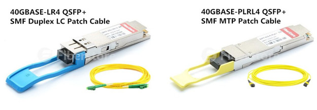
As for multimode QSFP+, it always works in 850nm wavelength which is only suitable for short distance applications. It has the ability to transmit 40G signals over OM4 at lengths up to 500m. Although it can’t transmit signals for long distance, it is capable to transmit many kinds of optical signals. As for the color of its compatible fiber optic patch cord, it can be orange, aqua or light blue. Besides, it usually uses MPO/MTP connector, but there are still some multimode QSFP+ with duplex LC connectors. For instance, QSFP-40G-CSR4 transceivers with MPO/MTP connector and QSFP-40G--UNIV transceivers with duplex LC connectors, as shown in the following figure.
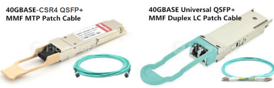
As we all know, the laser light source of SMF is very strong, while the transmission mode of SMF only causes little modal dispersion in the signal transmission. All these facts make single-mode QSFP+ perform with higher bandwidth and much longer transmission distances when transmitting signals. Compared with multimode QSFP+, it has a much higher performance in signal transmission.
As for multimode QSFP+, it is clearly different from the previous one. Multimode QSFP+ always works with MMF that has a much bigger core and usually uses wider wavelength of light. As the laser light source of MMF is not so strong as the previous one and there is a seriously large dispersion caused by the transmission mode of MMF, multimode QSFP+ can’t transmit signals for long distance. Based on these reason, multimode QSFP+ is much cheaper than single-mode QSFP+. Besides, it is capable to transmit many kinds of optical signals, while single-mode QSFP+ can only transmit one kind of optical signal.
No matter which QSFP+ transceivers you choose to deploy 40G Ethernet network, you should be noted a lot of things before installation. Firstly, you should ensure that the QSFP+ in both ends of the fiber patch cord are with the same wavelength. You can simply confirm it by the color of the modules that should be consistent. Secondly, aiming at data accuracy, short-wave QSFP+ modules should be better used with multimode patch cords (ie. aqua OM3 or OM4 fiber patch cord), while long-wave QSFP+ modules need to work with single-mode patch cords (ie. yellow fiber patch cord). Thirdly, do not over bend or winding fiber optic cables, which increases the attenuation of light in transmission. Finally, please use a dust plug to protect the optical bore when the QSFP+ is not working.
Single-mode QSFP+ and multimode QSFP+ have different transmission distance, light wavelength, connectors and fiber optic patch cord, which are the most important factors you should consider when making a choice. Except these factors, the costs for transceiver modules will be also considered. If you have a budget pressure and want to save more for deploying 40G Ethernet network, you can choose the compatible module without sacrificing any quality or reliability but only with a low cost.
Posted by: katherinewangfs at
08:11 AM
| No Comments
| Add Comment
Post contains 709 words, total size 6 kb.
November 21, 2016
As the number of cloud applications, big data services and virtualized workloads has increased dramatically over these years, the demand for more capacity and higher transmission speed becomes an urgent task for your network. For the sake of accommodating these applications in your system with higher data transmission rate and better performance, you are suggested to upgrade your network to 40G Ethernet. Hence, you can get a smoothly faster network without buffering that may cause a time delay. Here will introduce two 40G OSFP+ transceiver solutions for data center short distance transmission and analyze their features for you, which may be helpful when you deploy 40G Ethernet network for your system.
As we know, 40GBASE-SR4 QSFP+ transceiver and 40GBASE-SR BiDi QSFP+ transceiver are designed for short distance transmission, but their features are extremely different from each other, varying from working principle to cabling method. The transceivers in following figure are examples of these two kinds of 40G transceivers, Cisco QSFP-40G-SR-BD and Cisco QSFP-40G-SR4 for your reference.
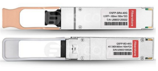
The word SR from 40GBASE-SR4 QSFP+ transceiver stands for short reach. For its name, it is easily to acquire that this kind transceiver is designed for 40G connectivity in a QSFP form factor. When working for a 40G data transmission, it can support the connection at lengths up to 150 meters over OM4 multimode fiber optic cables (MMF).
However, as the aggregation-layer fiber infrastructure is built for 10G connectivity in most data center networks that either supports direct connections between devices over LC-to-LC MMF, or uses LC-to-LC fibers to attach devices to patch panels, we should note that the regular duplex LC-to-LC fibers cannot be directly reused for 40G connectivity by using 40GBASE-SR4 QSFP+ transceiver.
The QSFP BiDi (bi-directional) transceiver was firstly published by Cisco, which has the ability to transmit 40G signals over duplex multimode fiber optic cables with LC connectors, addressing the challenges of fiber infrastructure. In contrast to 40GBASE-SR4 QSFP+ transceiver, it can support 40G connection over only one pair of duplex MMF cables, which allows 40G to be deployed by using the same infrastructure as 10G (10GBASE-SR) without the need to add any additional fibers. When transmitting 40G signals over a duplex OM3 MMF, it can support the transmission at lengths up to 100 meters. What’s more, it can reach 150 meters over OM4 MMF for 40G transmission.
The working principles of these two transceivers are not similar at all. As for the working principle of 40GBASE-SR4 QSFP+ transceiver, we can learn from the following figure. There are two independent sections, transmitter and receiver and 12 parallel fiber strands in a whole working process. The signal will be sent from the transmitter over 4 parallel fiber strands, while transmitted to the receiver over another 4 parallel fiber strands. Thereby 8 fiber strands are required for transmitting signals. Besides, 12-fiber MPO connectors are used in 40GBASE-SR4 QSFP+ transceiver, with 4 fiber strands wasted as shown in the following figure.
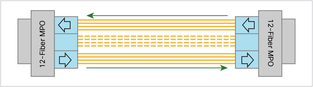
Instead of 12 parallel fiber strands with 12-fiber MPO connectors, there are only a pair of duplex MMF cables with duplex LC connectors in QSFP BiDi (bi-directional) transceiver. The duplex MMF cables offer two 20G channels to transmit and receive 20G signals simultaneously with different wavelengths, therefore an aggregated duplex 40G link over two duplex MMF strands shown can be accomplished without adding extra fiber cables. To better understand the working principle, the following figure shows how QSFP BiDi (bi-directional) transceiver transmit two 20G signals over two duplex MMF fiber cables to finish 40G connection.
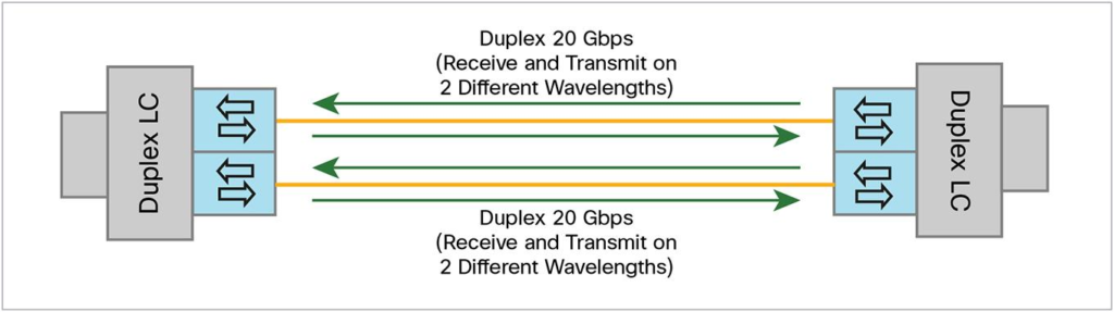
From what illustrated above, we can see that both the 40GBASE-SR4 QSFP+ transceiver and 40GBASE-SR BiDi QSFP+ transceiver are designed for short distance transmission with different features. Since there are 12 parallel fiber strands with 12-fiber MPO connectors in 40GBASE-SR4 QSFP+ transceiver, with additional products like MTP/MPO cassettes for better cabling, its cabling infrastructure method must be much more complicated than that of QSFP BiDi (bi-directional) transceiver. In contrary, QSFP BiDi (bi-directional) transceiver allows 40G to be deployed with the same infrastructure as 10G (10GBASE-SR) without any additional fibers. Hence, QSFP BiDi (bi-directional) transceiver could be a good choice for you to deploy 40G Ethernet network.
Posted by: katherinewangfs at
10:24 AM
| No Comments
| Add Comment
Post contains 715 words, total size 6 kb.
32 queries taking 2.0366 seconds, 99 records returned.
Powered by Minx 1.1.6c-pink.

