


November 29, 2016
Since data centers have been experiencing an great infrastructure change to achieve higher levels of performance and scalability, the demand for 100G Ethernet network increases day by day. To better accommodate this great change, there are several kinds of transceivers designed for deploying 100G Ethernet network, such as, CFP, CFP2, CFP4, QSFP28, CPAK, etc. Among these 100G optics, QSFP28 transceiver offers the optimal solution for the 100G migration with the lowest power consumption which is very commonly used at present. In this paper, it will introduce QSFP28 transceiver and analyze the reason why QSFP28 transceiver is so popular in 100G Ethernet network.
As the smallest 100G form factor transceiver, QSFP28 transceiver has the same size and lane number as 40G QSFP+ transceiver, which is implemented with four 25-Gbps lanes to achieve 100G transmission. With the design of an upgraded electrical interface, it is able to support signals rates up to 28 Gbit/s that makes the deployment of 100G Ethernet network as easy as that of 10G Ethernet networks.
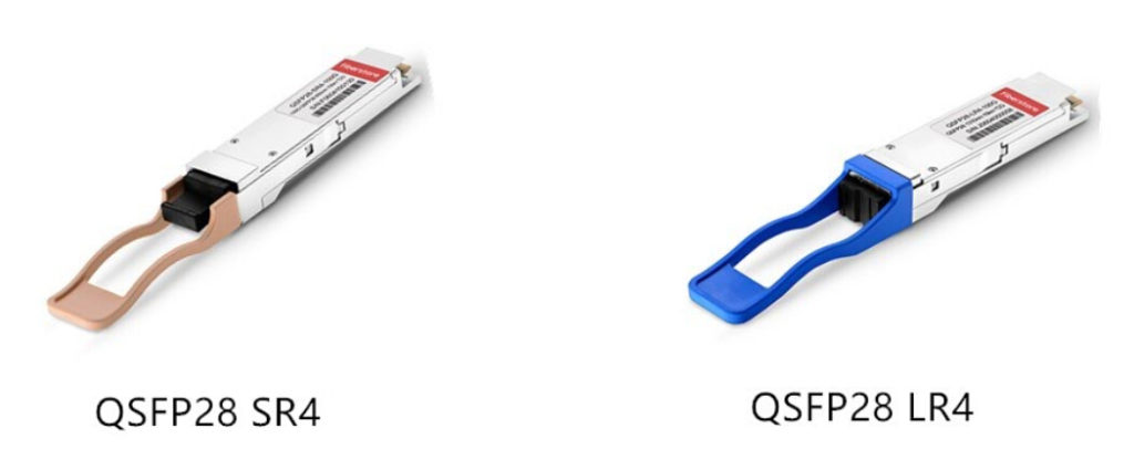
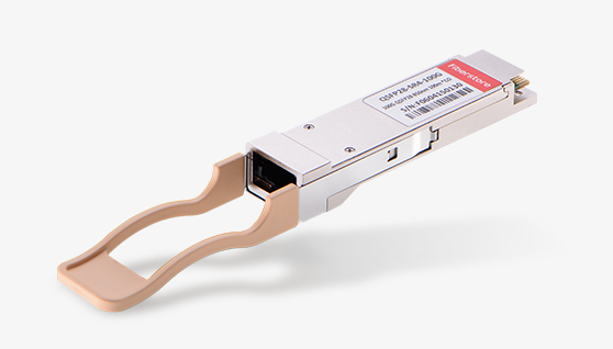
Generally, there are two types of QSFP28 transceivers, QSFP28 SR4 and QSFP28 LR4, which are used for different applications. As for QSFP28 SR4, it is suitable for 100G short distance transmission through multimode fiber up to 100 m. As for QSFP28 LR4, it is widely applied in 100G long distance transmission through single mode fiber, at lengths up to 10 km. The following figure shows the two types of QSFP28 transceivers for your reference.
There is no doubt that QSFP28 transceiver has a lot of advantages that make itself more popular than other 100G optics. In order to better deploy 100G Ethernet network, QSFP28 transceiver is designed with a strong improvement that increases port density and decreases power consumption with a lower cost, which will be illustrated detailedly in the following text.
Higher Port Density: As we know, the first generation of 100G transceiver is CFP, which is designed with a very large form factor. As for the next generations, CFP2 and CFP4, although their sizes decrease a lot, they are still larger than 40G QSFP+ transceiver. However, QSFP28 is published soon as the smallest 100G form factor transceiver with the same footprint and face plate density as QSFP+ transceiver. In general, with its advantage of high port density, we can install up to 36 QSFP28 on a 1RU switch on the front panel.
Lower Power Consumption: As for the general 100G optics, their power consumption ranges from 6 W to 24 W. In the contrast with these optics, QSFP28 transceiver transmits signals with the lowest power, less than 3.5 W. In short, QSFP28 transceiver is the most ideal solution for 100G transmission with the lowest power consumption at present.
Lower Cost: The deployment of 100G Ethernet network with QSFP28 transceiver can save a lot which mainly shows in the following aspects. Firstly, it can save considerable amount of money with the advantages of higher port density and lower power consumption. Secondly, it is implemented with four lanes, increasing the transmission capacity of every lane from 10G to 25G, thus it effectively decreases cost for each bit. Thirdly, both of its electrical and optical lanes work at the same speed that eliminates the costly gearbox found in CFP, CFP2 and CPAK. Finally, its way of migrating to 100G Ethernet network is also superior that can change from 10G-40G-100G to 10G-25G-100G or 10G-25G-50G-100G, much simplifying the cabling and saving the cost in data centers.
In short, QSFP28 transceiver will be more and more commonly used, ensuring data centers to scale 100G networks with the same simplicity as 10G networks. After knowing the advantages of QSFP28 transceiver, do you also want to achieve higher levels of performance and scalability by using QSFP28 transceiver for your system? If you only need a 100G short distance connection, you can choose QSFP28 SR4. And QSFP28 LR4 would be a good choice for 100G long distance transmission.
Posted by: katherinewangfs at
02:23 AM
| No Comments
| Add Comment
Post contains 670 words, total size 5 kb.
November 24, 2016
When choosing QSFP+ transceivers for designing 40G Ethernet network, you may hear the descriptions like "Single-mode QSFP+â€, "Multimode QSFP+â€. Are you familiar with these modules? What do these words stand for? What’s the difference between these two QSFP+ modules? Which one should you choose to deploy your 40G Ethernet network? And what should be noticed when using them?
In fact, the words single-mode and multimode here mean the different types of optical fibers that QSFP+ transceivers work with. For instance, single-mode QSFP+ means that QSFP+ transceivers run through single-mode fibers (SMF), while multimode QSFP+ will work with multimode fibers (MMF). In this article, we will have a discussion about the differences between the two QSFP+ transceivers and introduce the notice when using them.
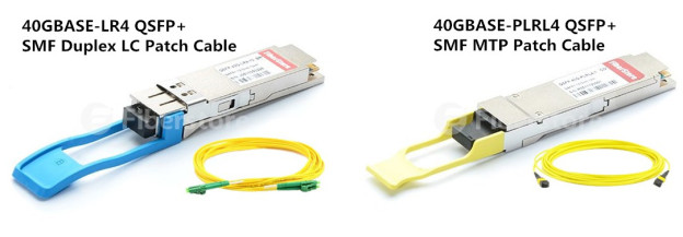
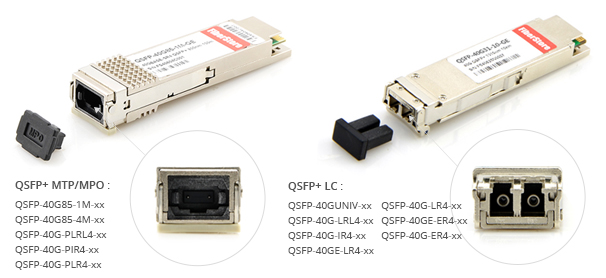
Generally, single-mode QSFP+ transceivers mainly work in 1310nm wavelength, mostly applied for 40G long distances transmission, such as, 1km, 2km, 10km and 40km. It can be divided into many types according to the different transmission distance, while the color of its compatible fiber optic patch cord is always yellow. As for its connector, it usually uses duplex LC connector, but sometimes works with MPO/MTP connector. You can take QSFP-40G-LR4 module and QSFP-40G-PLRL4 module as examples shown in the following figure.
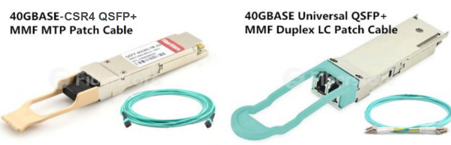
As for multimode QSFP+, it always works in 850nm wavelength which is only suitable for short distance applications. It has the ability to transmit 40G signals over OM4 at lengths up to 500m. Although it can’t transmit signals for long distance, it is capable to transmit many kinds of optical signals. As for the color of its compatible fiber optic patch cord, it can be orange, aqua or light blue. Besides, it usually uses MPO/MTP connector, but there are still some multimode QSFP+ with duplex LC connectors. For instance, QSFP-40G-CSR4 transceivers with MPO/MTP connector and QSFP-40G--UNIV transceivers with duplex LC connectors, as shown in the following figure.
As we all know, the laser light source of SMF is very strong, while the transmission mode of SMF only causes little modal dispersion in the signal transmission. All these facts make single-mode QSFP+ perform with higher bandwidth and much longer transmission distances when transmitting signals. Compared with multimode QSFP+, it has a much higher performance in signal transmission.
As for multimode QSFP+, it is clearly different from the previous one. Multimode QSFP+ always works with MMF that has a much bigger core and usually uses wider wavelength of light. As the laser light source of MMF is not so strong as the previous one and there is a seriously large dispersion caused by the transmission mode of MMF, multimode QSFP+ can’t transmit signals for long distance. Based on these reason, multimode QSFP+ is much cheaper than single-mode QSFP+. Besides, it is capable to transmit many kinds of optical signals, while single-mode QSFP+ can only transmit one kind of optical signal.
No matter which QSFP+ transceivers you choose to deploy 40G Ethernet network, you should be noted a lot of things before installation. Firstly, you should ensure that the QSFP+ in both ends of the fiber patch cord are with the same wavelength. You can simply confirm it by the color of the modules that should be consistent. Secondly, aiming at data accuracy, short-wave QSFP+ modules should be better used with multimode patch cords (ie. aqua OM3 or OM4 fiber patch cord), while long-wave QSFP+ modules need to work with single-mode patch cords (ie. yellow fiber patch cord). Thirdly, do not over bend or winding fiber optic cables, which increases the attenuation of light in transmission. Finally, please use a dust plug to protect the optical bore when the QSFP+ is not working.
Single-mode QSFP+ and multimode QSFP+ have different transmission distance, light wavelength, connectors and fiber optic patch cord, which are the most important factors you should consider when making a choice. Except these factors, the costs for transceiver modules will be also considered. If you have a budget pressure and want to save more for deploying 40G Ethernet network, you can choose the compatible module without sacrificing any quality or reliability but only with a low cost.
Posted by: katherinewangfs at
08:11 AM
| No Comments
| Add Comment
Post contains 709 words, total size 6 kb.
November 21, 2016
As the number of cloud applications, big data services and virtualized workloads has increased dramatically over these years, the demand for more capacity and higher transmission speed becomes an urgent task for your network. For the sake of accommodating these applications in your system with higher data transmission rate and better performance, you are suggested to upgrade your network to 40G Ethernet. Hence, you can get a smoothly faster network without buffering that may cause a time delay. Here will introduce two 40G OSFP+ transceiver solutions for data center short distance transmission and analyze their features for you, which may be helpful when you deploy 40G Ethernet network for your system.
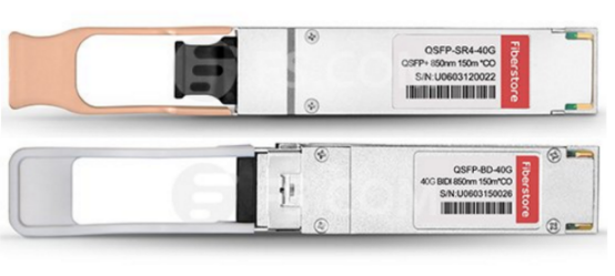
As we know, 40GBASE-SR4 QSFP+ transceiver and 40GBASE-SR BiDi QSFP+ transceiver are designed for short distance transmission, but their features are extremely different from each other, varying from working principle to cabling method. The transceivers in following figure are examples of these two kinds of 40G transceivers, Cisco QSFP-40G-SR-BD and Cisco QSFP-40G-SR4 for your reference.
The word SR from 40GBASE-SR4 QSFP+ transceiver stands for short reach. For its name, it is easily to acquire that this kind transceiver is designed for 40G connectivity in a QSFP form factor. When working for a 40G data transmission, it can support the connection at lengths up to 150 meters over OM4 multimode fiber optic cables (MMF).
However, as the aggregation-layer fiber infrastructure is built for 10G connectivity in most data center networks that either supports direct connections between devices over LC-to-LC MMF, or uses LC-to-LC fibers to attach devices to patch panels, we should note that the regular duplex LC-to-LC fibers cannot be directly reused for 40G connectivity by using 40GBASE-SR4 QSFP+ transceiver.
The QSFP BiDi (bi-directional) transceiver was firstly published by Cisco, which has the ability to transmit 40G signals over duplex multimode fiber optic cables with LC connectors, addressing the challenges of fiber infrastructure. In contrast to 40GBASE-SR4 QSFP+ transceiver, it can support 40G connection over only one pair of duplex MMF cables, which allows 40G to be deployed by using the same infrastructure as 10G (10GBASE-SR) without the need to add any additional fibers. When transmitting 40G signals over a duplex OM3 MMF, it can support the transmission at lengths up to 100 meters. What’s more, it can reach 150 meters over OM4 MMF for 40G transmission.
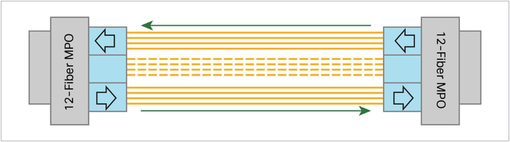
The working principles of these two transceivers are not similar at all. As for the working principle of 40GBASE-SR4 QSFP+ transceiver, we can learn from the following figure. There are two independent sections, transmitter and receiver and 12 parallel fiber strands in a whole working process. The signal will be sent from the transmitter over 4 parallel fiber strands, while transmitted to the receiver over another 4 parallel fiber strands. Thereby 8 fiber strands are required for transmitting signals. Besides, 12-fiber MPO connectors are used in 40GBASE-SR4 QSFP+ transceiver, with 4 fiber strands wasted as shown in the following figure.
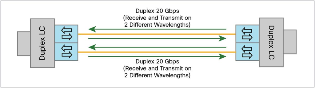
Instead of 12 parallel fiber strands with 12-fiber MPO connectors, there are only a pair of duplex MMF cables with duplex LC connectors in QSFP BiDi (bi-directional) transceiver. The duplex MMF cables offer two 20G channels to transmit and receive 20G signals simultaneously with different wavelengths, therefore an aggregated duplex 40G link over two duplex MMF strands shown can be accomplished without adding extra fiber cables. To better understand the working principle, the following figure shows how QSFP BiDi (bi-directional) transceiver transmit two 20G signals over two duplex MMF fiber cables to finish 40G connection.
From what illustrated above, we can see that both the 40GBASE-SR4 QSFP+ transceiver and 40GBASE-SR BiDi QSFP+ transceiver are designed for short distance transmission with different features. Since there are 12 parallel fiber strands with 12-fiber MPO connectors in 40GBASE-SR4 QSFP+ transceiver, with additional products like MTP/MPO cassettes for better cabling, its cabling infrastructure method must be much more complicated than that of QSFP BiDi (bi-directional) transceiver. In contrary, QSFP BiDi (bi-directional) transceiver allows 40G to be deployed with the same infrastructure as 10G (10GBASE-SR) without any additional fibers. Hence, QSFP BiDi (bi-directional) transceiver could be a good choice for you to deploy 40G Ethernet network.
Posted by: katherinewangfs at
10:24 AM
| No Comments
| Add Comment
Post contains 715 words, total size 6 kb.
November 17, 2016
Nowadays our network has a gluttonous demand for data, which brings a big challenge to Ethernet network. In order to meet the increasing demand for higher and higher data transmission rate, 10G, 40G, 100G and even 120G Ethernet Network are developed to be deployed for our system. Have you ever known how fast the data transmission speed is in 100G Ethernet network? Do you also want to deploy 100G Ethernet network for your system? Then, are you familiar with the transceivers for 100G Ethernet network? In this article, it will mainly introduce some commonly used 100G transceivers that will guide you to select the proper transceiver for your network if you want to make the 100G migration.
100G Ethernet network is a kind of computer networking technology developed for transmitting data at rates of 100 Gbit/s. To meet the increasing requirement of high speed in 100G Ethernet network, a series of 100G transceivers are designed for connecting cabling to the network at the same time. Among these 100G transceivers, CFP, CFP2, CFP4, and QSFP28 are most commonly used 100G transceivers that will be introduced in the following paragraphs.
CFP is also known as C form-factor pluggable transceiver. The word C represents the Latin letter C which means the number 100 (centum), as CFP module was primarily developed for 100G Ethernet network. It is published after SFP module, but has a higher performance to support the high transmission speed of 100 Gbit/s. As for its application, the electrical connection of a CFP can only use 10 x 10Gbit/s lanes in each direction (RX, TX), while its optical connection can support both 10 x 10 Gbit/s and 4 x 25 Gbit/s variants of 100Gbps interconnects. What should be noted is that 10 Gbit/s signals were far more realizable than 25 Gbit/s signals. As a result, CFP solution to achieve 100Gbps data rate is always working with 10 x 10Gbit/s lanes , which is the first choice for the sake of cost.
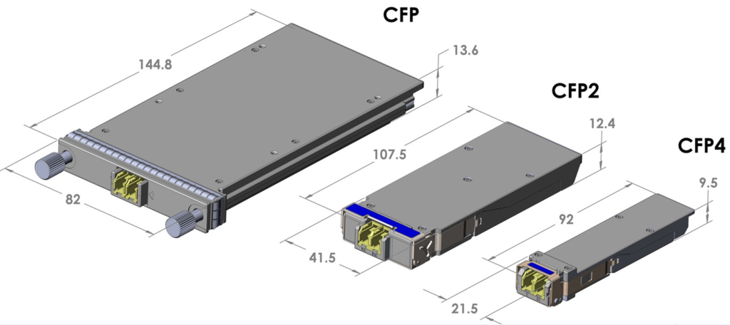
CFP has already met the requirement of 100 Gbps high data rate. However, for its big size, it is no longer fulfill the requirement of high-density data center. Take this into consideration, CFP2 and CFP4 are developed successively for higher performance and higher density in data center. As for the size comparison of these three transceivers, we can learn that CFP2 and CFP4 are 1/2 and 1/4 respectively in size of CFP from the following figure.
CFP2 and CFP4 transceivers are hot pluggable form factor transceivers that are designed for optical networking applications. Both of them can accommodate a wide range of power dissipations and applications. But they are greatly different in the following aspect. As for 100G CFP2 transceiver, it is used for interconnecting 100G Ethernet links that can reach 10 km over single mode fiber patch cables. And its interfaces can be various, 4 x 25Gbit/s, 8 x 25Gbit/s, 10 x 10Gbit/s, and 8 x 50Gbit/s. Clearly different from the previous one, 100G CFP4 transceiver is designed for 100 Gigabit Ethernet links with 4 x 25Gbit/s and 4 x 10Gbit/s interfaces.
Just like 40G QSFP+ Transceiver, 100G QSFP28 transceiver has also the same size and four channels, while the data transmission speed of its channel is increased from 10 Gbps to 25 Gbps to achieve 100Gbps data rate. As a four channel transceiver, it can transmit and receive 100 Gbps simultaneously. In contrast to other 100G CFP family, QSFP28 has increased the panel density and decreased power consumption which can save cost a lot. For this reason, it is more popular and commonly used for deploying 100G Ethernet network.
The requirements for higher fiber optical technology will never stop, so does the development of Ethernet network. As 100G Ethernet network is more and more widely deployed in today’s data center, more 100G transceiver solutions will be designed to achieve the aim of higher and higher density in data center.
Posted by: katherinewangfs at
10:23 AM
| No Comments
| Add Comment
Post contains 666 words, total size 5 kb.
November 14, 2016
Taking full advantages of low cost, high reliability, fast installation, easy maintenance and scalability, Ethernet Network becomes a very popular and commonly used LAN technology that has been developed for over 40 years and gets mature day by day. Under its continuous advancement and improvement, the data transmission rate has been increased greatly which causes the emergence of 10G, 40G, 100G and even 120G Ethernet Network. Among these kinds of Ethernet Network, there is no doubt that 10G Ethernet Network has become a commonplace for current network backbones, data centers, and server farms, supporting high-bandwidth, mission-critical applications. In this article, it will talk about why 10G Ethernet Network is so popular and which transceiver is most suitable for establishing 10G Ethernet Network.
It is well know that 10G Ethernet Network is developed for the purpose of ensuring faster data transmission and better network performance. As Ethernet technology is ever-accelerated and tended to be mature, 10G Ethernet Network has already become an desirable and much affordable choice with higher performance at lower cost.
10G Ethernet Network is designed with various advantages to cater for the ever-increasing applications which require considerable bandwidth to support large data transmission quickly. For instance, as an ideal technology to data transmission, it offers the best assurance for supporting forthcoming technologies and delivers utmost investment protection. Meanwhile, it is highly advantageous for Web caching, real-time application response, parallel processing and storage with its great bandwidth. Furthermore, compared to monthly communications link bills, the establishment of 10G Ethernet backbone is a one-time expense which will provide significant cost savings.
Nowadays, there exists indeed a need for 10G Ethernet Network. However, before deployment 10G Ethernet for your Network, you should consider lots of questions to design and make your network efficiently and smoothly, such as, selecting the right transceiver. The following will illustrate transceiver types for efficiently and smoothly establishing 10G Ethernet Network.
With the function of connecting the cabling to the network, the transceiver is an indispensable device for deploying 10G Ethernet network. At present, there are four kinds of transceiver used for 10G Ethernet network, XENPAK, X2, XFP and SFP+, as shown in the following figure.
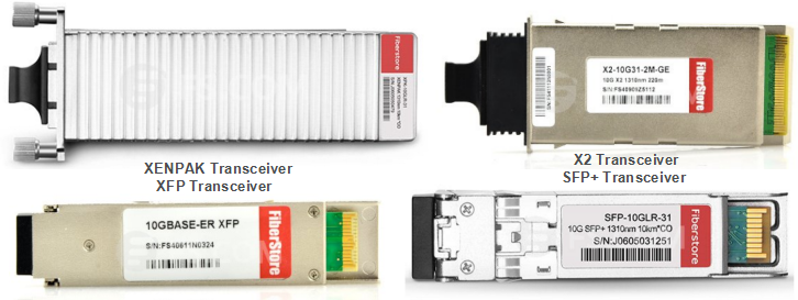
XENPAK—the first 10G pluggable transceiver came to the market which supports the 802.3ae standard transmission optics. It was publicly announced on March 12, 2001 that is large, bulky, hot pluggable and used mainly in LAN switches. This kind of transceiver also supports the new 802.3ak copper standard with vendors now producing transceivers to connect CX4 cables.
X2—smaller than XENPAK pluggable transceivers. Its form factor is about 2/3 the size of the XENPAK as shown in the figure above. With the same "hot pluggable†specifications and supporting all the 10GbE standards (including copper), the X2 form factor allows for more port density on switches. In short, it provides customers with a strong sense of assurance, which makes this technology the best choice for today and will have strong vendor support.
XFP—the newest pluggable transceiver on the market which was published on March 27, 2002. Its form factor is slightly larger than the SFP pluggable transceiver used for gigabit technology but smaller than the XENPAK transceiver. The XFP form factor will allow switch vendors to increase port density in a smaller area for cost savings.
SFP+—first published on May 9, 2006 which is designed on the consideration to increase the capacity of the existing SFP. It is smaller than XFP transceiver, but has the same size as SFP transceiver. In contrast to earlier XENPAK or XFP modules, SFP+ modules leave more circuitry to be implemented on the host board instead of inside the module.
Since 10G Ethernet network has become more and more commonly used, hope the information about transceiver solutions in this article would guide you to choose the proper transceiver for establishing your 10G Ethernet network. Apart from transceivers solutions, you should also consider the cabling solutions like SFP+ cable for the 10G migration.
Posted by: katherinewangfs at
09:35 AM
| No Comments
| Add Comment
Post contains 677 words, total size 6 kb.
November 10, 2016
With the development of Ethernet network, people have much higher requirements for data transmission rate and data capacity than ever before. In order to fulfill these requirements, 40G Ethernet network came into market, followed by a series of 40G fiber optical products, for instance, 40G QSFP+ transceivers, 40G QSFP+ to QSFP+ DAC, 40G MTP Conversion Cables. Among these 40G fiber optical products, 40G QSFP+ transceiver is designed for 40G migration as the most economic and effective module. If you want to upgrade your system into 40G Ethernet network, you may be interested in the information about 40G QSFP+ transceivers and its cabling methods.
In this post, it will talk about one of the basic 40G QSFP+ transceivers, 40G QSFP+ SR4 transceiver and introduce how to connect it to our network. Hence, the 40G migration with 40G QSFP+ SR4 transceiver for building your network can be processed flawlessly and smoothly.
QSFP is the acronym of Quad Small Form-factor Pluggable. From the words, we can easily learn that 40G QSFP+ SR4 is a compact, hot-pluggable transceiver that is being widely used for 40G transmission in short distances. As a 40G transceiver, its function is to connect networking equipment to a fiber optic cable or active or passive electrical copper, allowing 4x10 Gbit/s data rates.
Generally, 40G QSFP+ SR4 is designed to support 40G fiber optic transmission through multimode optical fiber, working on wavelength of 850 nm. It can transmit signals at lengths up to 100 meters through OM3 and 150 meters through OM4. Besides, there are 12-fiber parallel fiber terminated with MPO/MTP multi-fiber female connectors in QSFP+ SR4 to finish 40G transmission, occupying 4 fibers for sending signals, 4 fibers for receiving signals and 4 fibers wasted.
The cabling of QSFP+ SR4 transceiver is much more difficult than of SFP transceiver, which requires more cables and spaces. To better understand the connection method of 40G QSFP+ SR4, the following will introduce several high density QSFP+ SR4 transceiver cabling methods for your reference.
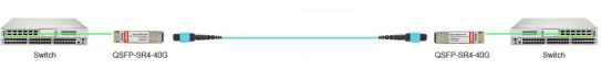
QSFP+ SR4 40G to 40G ApplicationsFrom the following figure, we can learn a simplest way of how 40G to 40G multimode transmission is being achieved by using QSFP+ SR4 transceivers. Two QSFP+ SR4 modules separately inserted in two 40G switches at one end, which are also connected by a length of multimode MTP trunk cable at the other end. Therefore, a 40G to 40G transmission is accomplished by using two QSFP+ SR4 transceivers.
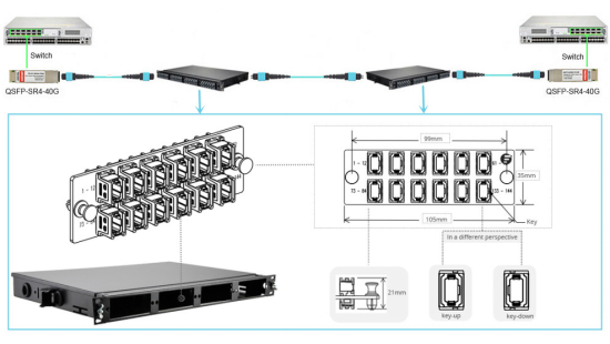
However, when you need lots of 40G connections at the same time and places, the simple cabling method is no longer suitable for cable management. In order to solve this, you are suggested to use a 48-port 1U rack mount MTP fiber patch enclosure, which can deploy up to four 12-port MTP fiber adapter panels for better and higher density cabling as shown in the following figure. Thereby, you can get 40G to 40G transmission with high density.
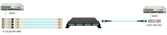
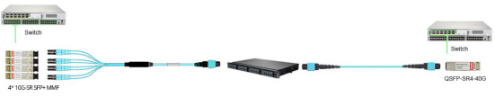
As we know, QSFP+ SR4 is a 12-fiber parallel optic transceiver which uses four fibers for sending signals and four fibers for receiving signals respectively, with 4 fibers wasted. It has the ability to finish the 40G to 10G transmission by separating the 40G signal into four 10G signals with four fiber optic cables at the 10G distribution end as shown in the following figure. In this transmission, one breakout MTP-8LC harness cable and one 1U 96-fiber enclosure with four HD MTP cassettes are suggested to be applied for better cable management. Besides, four 10G-SR SFP+ modules is also required to inserted in 10G switch/ports, connected to the corresponding LC ports on this fiber enclosure to make the transmission between 10G and 40G.
For higher cabling density, you can also use the 48-port 1U rack mount MTP fiber patch enclosure with an additional MTP-8LC harness cables to finish the 40G to 10G transmission as shown in the following figure. With the help of one 48-port 1U rack mount MTP fiber patch enclosure, the transmission from 40G to 10G can be done easier and managed better.
From this post, you can learn four cabling methods that illustrates how to connect QSFP+ SR4 modules to your network. Except these commonly used ones, QSFP+ SR4 modules can be applied into a variety of application with great flexibility, which depends on practical applications and cabling environments.
Posted by: katherinewangfs at
09:48 AM
| No Comments
| Add Comment
Post contains 742 words, total size 6 kb.
November 07, 2016
As WDM revolution has already occurred with unanticipated swiftness, WDM technology is largely used in a really fast manner, dramatically promoting the network for high-volume data transmission over a single fiber cable. Have you ever wondered how does WDM technology work? What’s the difference between CWDM and DWDM technology? Which one is the most suitable for your network? To better understand CWDM and DWDM technology, this post will study the working principle of WDM technology and analyze the detailed difference between CWDM and DWDM technology.
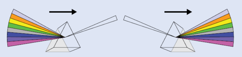
Have you ever heard about the working principle of the prism? When a white light beam with different wavelengths pass through the prism, there should be a light dispersion. It will be changed into several light beams and leave the prism at different angles, just like a rainbow. To the contrary, if several light beams with different wavelengths pass through the prism, it will be changed into a white light beam. The following figure shows the details of how does the prism work.
The working principle of WDM technology is similar to the above-mentioned principle. Without using additional fibers, WDM technology uses a multiplexer at the transmitter to combine multiple signals together, and a demultiplexer at the receiver to split them apart as shown in the following figure, so that multiple signals can be transmitted over a single fiber cable.
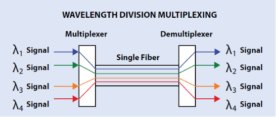
That’s to say, optical signals with different wavelengths are combined at the transmitter firstly, then will be transmitted together through the single optical fiber. Finally, the combined signals will be split into multiple signals with differing wavelengths again when arriving at the receiver. In the whole transmission process, each signal with its own wavelength will not interfere with each other. Therefore, the capacity of a fiber link can be expanded by simply putting the multiplexer and demultiplexer at each end.
WDM technology is very efficient and largely used that enables the capacity of the network to be expanded without more fibers. In general, it can be divided into two types, CWDM (coarse wavelength division multiplexing) and DWDM (dense wavelength division multiplexing), both of which are indispensable technologies to increase capacity on the fiber links. However, there are many differences between the two types, which vary from wavelength spacing to transmission distance.
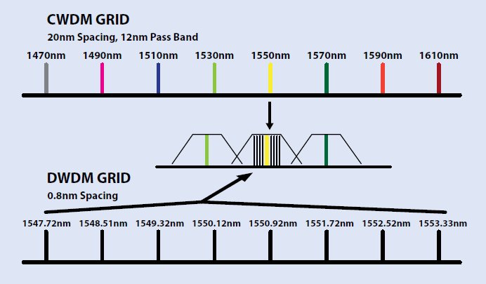
Wavelength SpacingCWDM and DWDM are divided on the basis of different wavelength patterns, while the words "coarse†and "dense†reveal the difference in channel spacing. As for CWDM, it has the capability to carry up to 16 channels on a single fiber in the spectrum grid from 1270 nm to 1610 nm with a 20nm channel spacing. As for DWDM, it has a narrower channel spacing, 0.8 nm, which is able to transmit up to 160 channels from the wavelengths of 1525 nm to 1565 nm (C-band) or 1570 nm to 1610 nm (L-band). In comparison, the denser spacing and more channels allow DWDM to transmit more optical signals over the same fiber than CWDM. For the basic difference between CWDM and DWDM, you can take the following figure as reference.
CWDM and DWDM use the same working principle to multiplex different wavelengths of optical signal via a single fiber, but differ in applications for the ability to amplify the multiplexed signals. As CWDM has no ability to amplify the signals, it is always used in short distance transmission that can support the transmission at lengths up to 160 km. However, DWDM is designed for longer haul transmission, which can expand greater maximum capacity and transmit the signals longer. Thereby, CWDM is always the first choice for short distance applications, while DWDM could be the priority for long distance transmission.
Manufacturing CostCompared to DWDM, CWDM with uncooled laser uses electronic tuning that is easier to be manufactured with lower cost. Why? Because DWDM with cooled laser is more difficult to accommodate temperature tuning due to the non-uniform temperature distribution in a very wide wavelength, which results in high cost. Meanwhile, DWDM has a much narrower channel spacing which requires more sophisticated transceiver designs. Hence, the manufacturing cost of DWDM is much higher than of CWDM. Typically, a DWDM product is four or even five time more expensive than a CWDM counterpart.
With its advantage of high-volume data transmission over a single fiber cable, WDM technology becomes more and more commonly used and plays an important role in facing the increasing demands of today’s network. Along with the constant development and maturity of WDM technology, it is divided into CWDM and DWDM that are indispensable technologies with different features. You are suggested to choose the suitable one for your network according to their features, such as, transmission distance, channel numbers.
Posted by: katherinewangfs at
10:19 AM
| No Comments
| Add Comment
Post contains 800 words, total size 6 kb.
November 03, 2016
Nowadays, the demands for data transmission rate and data capacity become much higher than ever before, which makes 40G Ethernet network more and more prevalent. Under this inevitable trend, 40G Quad Small Form-factor Pluggable (QSFP+) transceiver is designed for 40G migration as the most economic and effective module. Do you have a good knowledge about 40G QSFP+ transceiver? Are you interested in upgrading your system into 40G Ethernet network? If yes, there is an important and basic problem you need to consider and deal with before the migration. Which kind of fiber patch cable is the most suitable and cost-efficient for connecting your 40G QSFP+ transceiver?
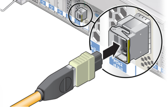
As we all know, switches are need to be connected so as to form the whole 40G transmission network. How to connect these switches? As a basic component in the connection, fiber patch cable plays an indispensable role in connecting 40G QSFP+ transceivers which are plugged in Ethernet switches. Then the whole connection can be done, which is shown in the following figure for your reference.
Considering that the quality of the connection will largely affect the reliability and stability of the whole 40G network, the selection for fiber patch cable should be a priority in 40G migration. Since the connectivity of 40G is much more complex than ever, this article will provide the fiber patch cable selection guide as detailed as possible for connecting 40G QSFP+ transceivers.
Choosing the proper fiber patch cable becomes a big issue in 40G network not only because of the switch connections necessity, but also because of the transmission principle of the fiber optic signals and the high density trend of 40G transmission. To ensure the quality of the whole 40G network, two factors should be taken into consideration when selecting fiber patch cable, which are cable type and connector type.
As the performances of optical signals are completely distinct over different fiber optic cables, selecting the most suitable cable type is essential. In principle, all the fiber optic cables can be used in 40G network. But if the data transmission rate increases, the optical signal transmission distance will get shorter. Hence, the longer the signal can be transmitted by fiber optic cable, the higher the performance of fiber optic cable will be.
As a result, OM3 patch cable and OM4 patch cable are suggested for connecting 40G QSFP+ transceivers in short distance, while the single mode fiber patch cable is the best choice for long transmission in 40G network. As for the two upgraded multimode cables, OM3 can support 40G network at lengths up to 100 meters and OM4 can support 40G network longer, up to 150 meters. Meanwhile, if you want to set up a long distance transmission in 40G network, you are suggest to choose single mode fiber patch cable that can transmit signals up to 10km.
The selection of connector type of the fiber patch cable depends on the interface of 40G QSFP+ transceiver. At present, there are two interfaces commonly adopted by 40G QSFP+ transceiver which are MTP interface and LC interface. In short transmission application, 40G QSFP+ transceivers with MPO interface are usually used, thereby the patch cable with MTP connectors should be also selected. In long transmission application, 40G QSFP+ transceiver is always with LC interface, so that patch cable with duplex LC connector should be used.
However, there are several 40G QSFP+ transceivers, for instance, 40GBASE-PLR4 and 40GBASE-PLRL4, which have MPO interfaces to support long transmission distance. If you choose these 40G QSFP+ transceivers for long distance transmission, the patch cables for connection should be also with MPO connectors.
When selecting the right fiber patch cables for 40G QSFP+ transceivers, both cable type and connector type must be considered that are closely related to transmission distance, 40G network flexibility and reliability. Hope the selection guide for fiber patch cable in this paper is helpful for you to design your 40G Ethernet network.
Posted by: katherinewangfs at
03:25 AM
| No Comments
| Add Comment
Post contains 679 words, total size 5 kb.
November 01, 2016
With the fast development of the optical network, the demand for wider bandwidth and faster data transmission rates over farther distances are increasing day by day, which makes more and more fiber cables need to be installed when the optical network is designed. However, once the available fiber infrastructure is exhausted and can’t meet the increasing communication need any more, laying more fibers would become an impracticable or uneconomical method. Thereby, new capacity for the network needs to be created. In order to solve this, experts try to fall back on two new methods to expand the capacity of our network: increasing system bitrate to multiplex more signals and using WDM (wavelength division multiplexing) technology.
It is well known that both increasing system bitrate to multiplex more signals and using WDM technology can expand the capacity of our network. But the fact is that WDM technology is more commonly used for expanding the capacity of our network. What makes WDM technology so popular in optical network? What’s the advantage of WDM technology? The following will introduce the two methods of expanding the capacity of our network and seek the differences of the two methods.
- Increasing System Bitrate
Nowadays, most of our systems have already worked in 2.5 GB network. If we want to increase our system bitrate to multiplex more signals for expanding capacity, we should upgrade our system to 10 GB network. However, the upgrading process requires changing out all the electronics in our network which should be an expensive project. Taking the high upgrade cost into consideration, it is not recommended to expand capacity by increasing system bitrate to multiplex more signals. - Using WDM Technology
In contrast to upgrading our system, using WDM technology to expand the capacity of our network should be a quite advisable, cost-effective way that doesn’t require more fiber cables or changing out the electronics in our network. WDM technology takes great advantage of the enormous bandwidth of the optical fiber and makes bidirectional communications via one strand of fiber possible. To be brief, WDM technology creates virtual fibers to transmit data, which is the optimal method to expand capacity in optic network at present. As WDM technology is developed fast and tended to be mature, it is strongly advised to use this technology for promoting the network with high-volume data transmission over one single optical fiber.
The word of WDM stands for wavelength-division multiplexing. From its name, it is easy to know that the technology is using different wavelengths of light from a laser or a LED to multiplex two or more optical carrier signals over a single optical fiber. In its working process, without using additional fibers, optical carrier signals with different wavelengths are combined at the ingress, then transmitted together through the single optical fiber, and finally separated into individual signals with differing wavelengths at the express again as shown in the following figure.

At present, there are two types of WDM technology, CWDM (coarse wavelength division multiplexing) and DWDM (dense wavelength division multiplexing), both of which are indispensable and popular technologies to expand capacity on the fiber links. To some extent, WDM technology strongly multiplies the capacity of the network that plays an important role in meeting the increasing requirement of modern network.
The WDM revolution has already occurred with unexpected swiftness, which is more popular and commonly used for expanding the capacity than increasing system bitrate in today’s network. Although WDM technology is lack of a long history, the maturity of the technology have been realized WDM systems tailored specifically to the metropolitan area, providing high bandwidth and high capacity at a relatively low cost.
Posted by: katherinewangfs at
01:37 AM
| No Comments
| Add Comment
Post contains 632 words, total size 5 kb.
32 queries taking 0.0818 seconds, 77 records returned.
Powered by Minx 1.1.6c-pink.

