


June 14, 2017
Optical transponder is also referred to as WDM transponder, wavelength-converting transponder or OEO (Optical-Electrical-Optical) 3R (re-timing, re-shaping, and re-amplifying) converter, and the word "transponder†is named according to the combination between transmitter and responder. It is an important unit in WDM system which main function is to convert the wavelength and the pattern of the optical signals and amplify the optical signals for long-haul transmission. At present, the optical transponder unit is commonly used in 10G connections including SFP+ to XFP, SFP+ to SFP+ and XFP to XFP fiber connections, and 40G QSFP+ to QSFP+ connections.
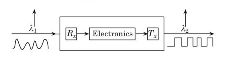
Working Principle of Optical TransponderThe optical transponder is designed to automatically receive a signal, amplify it and then retransmit the signal with another wavelength, without changing the content of the signal, which enables the different system to be connected. For instance, a 10G DWDM system can be deployed on the basis of a normal 10G system if using the optical transponder to convert a 850nm signal into a 1550nm one. What’s the working principle of the optical transponder? In general, when an optical input signal passes through the optical transponder, it will be firstly converted into an electrical one. Then a logical copy of the input signal is generated that features a new amplitude and shape and is used for driving the transmitter. Finally, an optical output signal with a new wavelength would be generated, as shown in the following figure.
As mentioned above, the optical transponder unit plays an important role in WDM system, which is very welcomed when deploying a CWDM or DWDM system on the basis of a normal system. It is well known that 850nm, 1310nm or 1550nm are used in a normal system for optical signal transmission, while CWDM or DWDM wavelengths are applied in a CWDM or DWDM system. Hence, if we want to transmit the normal signals to a CWDM or DWDM system, the optical transponder should be required that enables the normal wavelengths to be converted into CWDM or DWDM ones without changing the signal data. Here shows a wavelength conversion case by using the optical transponder.
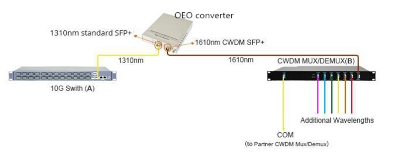
We can learn from the case that a 10G-LR 1310nm SFP+ module is connected to a 10G switch on site A, while a 10G CWDM SFP+ module working on 1610nm is used with the CWDM Mux Demux on site B. As the 10G 1310nm signal from site A is required to be transmitted to the existing CWDM system on site B, a two SFP+ ports optical transponder should be used for converting the 10G 1310nm signal into a 10G 1610nm CWDM signal. To achieve this, another 10G-LR 1310nm SFP+ module and 10G CWDM 1610nm SFP+ module should be inserted into the 10G SFP+ to SFP+ optical transponder, separately. Furthermore, fiber patch cables are required to link the two 10G-LR 1310nm SFP+ modules and two 10G CWDM 1610nm SFP+ modules together, so that a complete link for wavelength conversion can be done.
ConclusionThe optical transponder is an important component in WDM system that makes the wavelength conversion easy, so that the signal data can be transmitted from a normal system to a WDM system. For instance, with the use of the optical transponder unit, a 1310 signal from a 10G fiber optical network can be converted into a 1610 CWDM signal and transmitted to the 10G CWDM network. If you are facing the problem about wavelength conversion for connection between a normal network with a WDM network as noted above, the optical transponder is quite recommendable for you.
Posted by: katherinewangfs at
08:08 AM
| Comments (5)
| Add Comment
Post contains 605 words, total size 5 kb.
June 08, 2017
Currently, more and more users choose to deploy DWDM networks on the basis of their existing networks, as the normal network can’t afford enough capacity for their daily use. Considering that there may be some confusion for designing the DWDM networks, this paper will mainly introduce the basic knowledge of DWDM technology and analyze the difference between SDH and DWDM technology. To better understand the DWDM technology, this paper will also guide users to deploy two common kinds of DWDM network. Hope the DWDM information in the paper would be useful for deploying a smooth DWDM network with higher transmission rate and capacity.
Introduction to DWDM TechnologyDWDM technology is an ideal solution to address the capacity-hungry issue, which can multiplex several wavelengths for transmission different kinds of signals through one single fiber. In principle, the network utilizing DWDM technology enables carry up to 140 channels for transmitting signals, finally achieving high bandwidth transmission. As for the DWDM components, it basically includes DWDM multi-channel Mux/Demux, dispersion compensation module, fiber optic amplifier, optical transponder, and so on.
SDH vs DWDM TechnologyAs we know, SDH is the technology combining more than one lower-speed electrical or optical signals into a single higher bit rate signal with a single wavelength for transmission over a single fiber or wire. In the network utilizing SDH technology, Time division multiplexing (TDM) or statistical TDM is used, which means the signals in SDH network will be received by distributed across time slots. As for the DWDM technology, it uses wavelength multiplexing method, so that the signals can arrive at the receiver simultaneously. In the DWDM network, the DWDM multi-channel Mux/Demux mentioned above is the key components that can give different wavelengths to the different optical signals and multiplex them, so that the integrate signal with different wavelengths can be transmitted over a single fiber.
In short, SDH uses time division multiplexing, while DWDM works with wavelength division multiplexing. Compared to the SDH technology, DWDM can give different wavelengths to the optical signals, which allows the signals to be transmitted with their own speed and protocol and arrive at the same time. Besides, the SDH network can transmit both electrical or optical signals, while DWDM network only supports optical signal transmission.
Common DWDM Network DesignsGenerally speaking, there are many kinds of DWDM networks with topological configurations, each of them has different requirements and can be used for different applications. They are basically DWDM point-to-point network, fully connected mesh network, star network, ring network and hybrid DWDM network consisting of stars and/or rings that are interconnected with point-to-point links. The following will mainly introduce the two most common DWDM networks, point-to-point network and ring network for your reference.
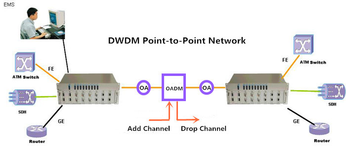
DWDM Point-to-Point Network: this kind of DWDM network is always deployed for long distance transmission with fast transmission speed, high bandwidth, great reliability and path restoration capability. The numbers of fiber optic amplifier used in this DWDM network is often less than 10, while the transmission distance can be up to several hundred kilometers. If optical add-drop multiplexer (OADM) is used, channels can be dropped or added along the path of the DWDM link. To better know the DWDM point-to-point network, here offers a figure that shows a DWDM point-to-point network design with the use of DWDM multi-channel Mux/Demux, OADM and fiber optic amplifier.
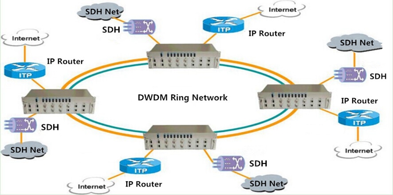
DWDM Ring Network: In general, this kind of DWDM network is often applied in local or metropolitan areas that can support the DWDM network at lengths up to dozens of kilometers. A basic DWDM ring network is shown in the following figure that has many nodes fully interconnected by the fiber, and sometime there are two fiber rings in a DWDM ring network which are deployed for protecting the network. Besides, the DWDM components like DWDM multi-channel Mux/Demux, OADM and optical amplifier are also required in the DWDM ring network.
DWDM technology is an economical solution for transmitting multiple signals through one fiber, which can solve the problem of insufficient capacity in your network. In contrast with SDH technology, DWDM technology enables the optical signals to be transmitted fast and arrive at the receivers simultaneous, while offering much higher capacity and transmission rate. If you are interested in DWDM technology, you can visit FS.COM where the wholesale DWDM Mux Demux, OADM and optical amplifier are available. It is recommended because of the good DWDM Mux Demux, OADM and optical amplifier price and quality.
Posted by: katherinewangfs at
08:10 AM
| Comments (6)
| Add Comment
Post contains 747 words, total size 6 kb.
June 01, 2017
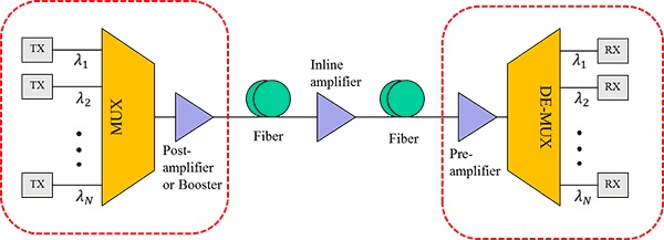
EDFA amplifier is the most common optical amplifier, used for boosting optical signals in optical applications, especially the DWDM systems. It is the key amplification device deployed in the optical system to enhance the signal power, so that the optical transmission distance can be greatly extended. Undoubtedly, the EDFA amplifier is an ideal choice for long-haul DWDM system. But how does it work for extending DWDM system? As shown in the following figure, EDFA amplifier can be placed at the transmitting side of the DWDM link, any intermediate point along the transmission DWDM link and the receiving end of the DWDM link, separately working as booster amplifier (or post-amplifier), in-line amplifier (or optical line amplifier) and pre-amplifier for optimizing the DWDM system reach. Let’s study the related knowledge in details.
EDFA amplifier is a kind of optical amplifier that can directly amplify any input optical signal without the need of optical-electrical-optical conversion. It can not only save the cost for long-haul transmission, but also reduce the signal loss and unwanted noise, compared to the traditional optical-electrical-optical amplification. As the fiber attenuation limits the reach of a non-amplified fiber link to about 200 km, EDFA amplifier is an ideal choice for building wide area purely optical networks.
How Does EDFA Amplifier Work?As mentioned before, EDFA amplifier can be deployed in three places of the DWDM link to make the power compensation, the transmitting side of the link, the intermediate point along the link and the receiving end of the link. If placed at the transmitting side, it can be called as booster optical amplifier or post-amplifier, offering high input power for the wide fiber span. If placed at the intermediate point along the link, you can call it in-line amplifier or optical line amplifier. The optical line amplifier is used for compensating the fiber loss in the transmission link. When you call it pre-amplifier, it must be deployed in the receiving end, for boosting the signal power to the the necessary receiver level. The following will introduce these three different deployments of EDFA amplifier and how does the it work in the three link.
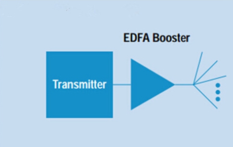
Placed at the Transmitting Side: in this application, we always call EDFA as booster optical amplifier that features high input power, high output power and medium optical gain. It can directly amplify the aggregated optical input signal multiplexed by the DWDM Mux Demux, to achieve DWDM network transmission distance extension. By placing the EDFA amplifier at the transmitting side of the DWDM link, the transmitted signal power can be enhanced to the necessary transmitting level and the optical loss caused by the laser and optical fibers can be also compensated. Hence, the EDFA booster optical amplifier is always deployed when the DWDM Mux Demux attenuates the signal channels.
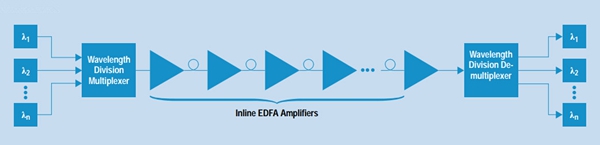
Placed at the Intermediate Points: as shown in the figure below, the EDFA in-line amplifier can be put at any intermediate point along the long transmission link. This kind of EDFA optical amplifier is designed with low input power, high output power, high optical gain and low noise figure, which are normally deployed every 80-100 km to amplify signals between any two link nodes on the main optical link, with the aim of compensating the loss caused by fiber transmission and other factors. Thereby, the optical signal level can stay above the noise floor.
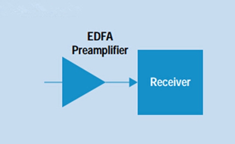
Placed at the Receiving Side: EDFA optical amplifier operates at the receiving side of the link is also referred to as pre-amplifier, which has the features of medium to low input power, medium output power and medium gain. This optical pre-amplifier put before the receiver end of the DWDM link is to compensate for losses generated by the demultiplexer located near the optical receiver. With the use of pre-amplifier, the optical signal level can be enhanced before the photo detection, hence improving the receive sensitivity for a long-haul fiber DWDM link.
In conclusion, the EDFA optical amplifier can be deployed as booster optical amplifier in the transmitting side of the DWDM link to provide high input signal power for the wide fiber span. It can also work as in-line amplifier at the intermediate point along the link for compensating the fiber loss in the transmission link. What’s more, as the pre-amplifier deployed in the receiving end, it amplifies the signal power to the the necessary receiver level. No matter where the EDFA optical amplifier is deployed in the DWDM link, the signal power can be always enhanced for making a longer DWDM system.
Posted by: katherinewangfs at
03:38 AM
| Comments (6)
| Add Comment
Post contains 762 words, total size 7 kb.
36 queries taking 0.1313 seconds, 83 records returned.
Powered by Minx 1.1.6c-pink.

