


February 27, 2017
As the most commonly used module in 100G Ethernet network, QSFP28 transceiver can be fitted with various of 100G interfaces to meet the requirements of different applications. For instance, the most basic 100G interfaces, 100GBASE-SR4 always used for short distance transmission, no longer than 100 m, and 100GBASE-LR4 highly recommendable for long-haul optical transmission, with the lengths up to 10 km, occupy the majority of the 100G market. Considering that, if we want to deploy the 100G Ethernet network with the transmission distance longer than 100 m but shorter than 10 km, the QSFP28 100GBASE-SR4 transceiver can’t satisfy the requirement and the QSFP28 100GBASE-LR4 transceiver is not the most cost effective one. In order to deal with the mentioned applications, the 100GBASE-PSM4 and 100GBASE-CWDM4 interfaces for QSFP28 transceivers came into market, expected to be the optimized, alternative solutions for 100G Ethernet network in data center.
It is well known that 100GBASE-SR4 and 100GBASE-LR4 defined by IEEE are the most popular 100G interfaces, which can support the 100G network with too short or too long distance. However, for data center managers, they would like to choose the QSFP28 transceiver that can transmit the 100G signal within 500m or 2km maximum distance. Hence, the two basic 100G interfaces are not the most suitable ones for them.
Under this condition, MSA (Multi-Source Agreement) strategy brings a mid-reach solution to the 100G market, and the PSM4 and CWDM4 interfaces for the 100G QSFP28 transceivers are published in this revolution. Compared to the basic 100G interfaces, these two non-IEEE defined interfaces can not only support 100G network with longer distance than 100GBASE-SR4, but also cost less than 100GBASE-LR4. There is no doubt that these two interfaces can gradually become more and more popular due to these two advantages.
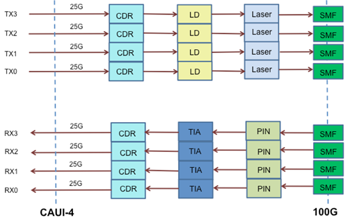
QSFP28 transceiver with PSM4 interface can be also called PSM4 QSFP28 transceiver. It is designed with four lanes of parallel ribbon fiber, carrying serialized data through single mode fiber at a rate of 25 Gbps per lane, which totally achieves the 100G transmission, as shown in the following figure. With the use of 12 fiber MTP/MPO connectors, it can support the 100G network with the distance limited to 500 m. As for its light source, it is a single uncooled distributed feedback (DFB) laser with 1310nm wavelength. Hence, in its working process, there should be either a directly modulated DFB laser (DML) or an external modulator for each single mode fiber.
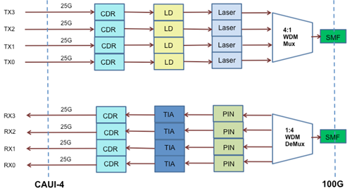
Instead of parallel technology, QSFP28 transceiver with CWDM4 interface specially uses the CWDM technology, which makes only one single mode fiber required for data transmission. Meanwhile, it can support the 100G transmission at lengths up to 2 km. In its working process, the optical multiplexer and de-multiplexer are required to separate and combine the four 25G signals which operate around 1310nm. Besides, the connector in the CWDM4 QSFP28 transceiver is also different, duplex LC connector. To better know the working principle of CWDM4 QSFP28 transceiver, you can learn it from the figure below.
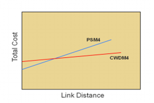
After knowing the basic knowledge of PSM4 and CWDM4 QSFP28 transceiver, let’s compare these two kinds of 100G transceivers with different interfaces and find which one is more cost effective. As the components like multiplexer and de-multiplexer fitted in the CWDM4 QSFP28 transceiver are very expensive, the cost for QSFP28 transceiver with CWDM4 interface is much higher than that of the PSM4 one. But if the whole 100G connection cost is taken into account, the answer should depend on the link distance. As it can be seen in the following figure, PSM4 QSFP28 starts with a lower cost due to its lower transceiver cost, but as the connection distance increases, its total cost climbs up very fast due to the fact that it uses 8 optical fibers. Hence, if you want to deploy the 100G network with a short distance, you are highly suggested to choose the QSFP28 transceiver with PSM4 interface. Or the QSFP28 transceiver with CWDM4 interface is the best choice for you, as a cost effective transceiver solution. In addition, if you have any interest, the following article offers more information about these two kinds of interfaces for QSFP28 transceivers.
Posted by: katherinewangfs at
08:43 AM
| Comments (5)
| Add Comment
Post contains 724 words, total size 6 kb.
February 23, 2017
Since the 10G/40G Ethernet network can not satisfy the development of the fiber technology, data centers around the world spare no effort to explore preferable options for higher network speed and larger bandwidth. The 100G Ethernet network was published under that situation, and accordingly, a series of related solutions like QSFP28 cables and QSFP28 transceivers are designed for data center upgrade. In fact, QSFP28 cables and QSFP28 transceivers are not the most popularly used but also useful solutions, with the aim of upgrading 10G/40G Ethernet network to 100G Ethernet network, which will be studied in the this post.
QSFP28 cables like QSFP28 DACs and QSFP28 AOCs and QSFP28 transceivers like QSFP28 SR4 and QSFP28-LR4 are the widely used solutions for data center upgrade, both of which highly surpass their corresponding traditional devices, such as, QSFP+ cables and QSFP+ transceivers. For the detailed information about these QSFP28 cables and QSFP28 transceivers, let’s explore them in the following text.
QSFP28 CablesQSFP28 cables are the cost-efficient solutions to deal with the issues caused by connecting cables with transceivers, which are able to support the 100G Ethernet network by directly connecting 100G devices together. Thereby, with the use of QSFP28 cables, a lot of connection issues can be eliminated or avoided and the whole 100G connection can be accomplished easily and fast.
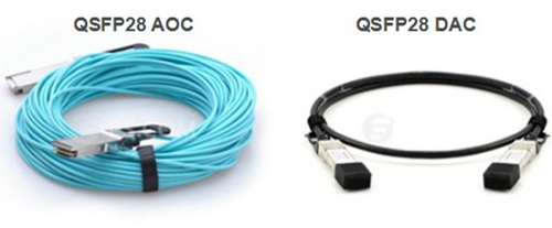
At present, the QSFP28 cables can be simply divided into direct-attach copper cables (DACs) and active optical cables (AOCs), as shown in the following figure. As for the QSFP28 DACs, they can be available at the lowest cost, while only suitable for the applications within 15m transmission distance. They are easily found in the racks of the data center and can be also used for chassis-to-chassis interconnect in large switch and routers. As for the QSFP28 AOCs, they are much lighter than the QSFP28 DACs. What’s more, the QSFP28 AOC can transmit the 100G signal with a much longer distance, 100 m or even more.
Compared to the QSFP28 cable mentioned above, QSFP28 transceiver could be much more complicated which is implemented with four 25-Gbps lanes for achieving 100G transmission. QSFP28 transceiver is the smallest 100G form factor transceiver that has the exact same footprint and faceplate density as 40G QSFP+ transceiver. Although it keeps the physical dimension of its predecessor, it has a great improvement in the panel density and also highly decreases power consumption. From the figure below, you can learn the two common types of QSFP28 transceivers, QSFP28 SR4 and QSFP28 LR4.
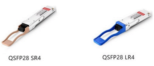
As for the QSFP28 SR4 transceiver, it came into the market firstly to transmit the 100G signal through multimode fiber (MMF) for a short transmission distance. In details, 100G signal supported by the QSFP28 SR4 transceiver can be transmitted through OM3 MMF at length up to 70 m, while 100 m through OM4 MMF. Meanwhile, it features with MTP interface, which allows for 4×25G dual way transmission over 8 fibers.
Clearly different from the QSFP28 SR4 transceiver, QSFP28 LR4 transceiver is specifically designed for 100G long distance transmission, as the letter L (long) in its name implies. This kind of QSFP28 module with duplex LC interface always works on single-mode fiber (SMF), supporting the 100G dual-way transmission up to 10 km. When it is working, WDM technology will be used for the 4×25G signals long transmission, and each 25G signal will be transmitted over four different wavelengths.
From this paper, you can learn two kinds of commonly used QSFP28 cable solutions, QSFP28 DAC and QSFP28 AOC. QSFP28 DAC is always used for 100G short distance transmission, within 15 m, while QSFP28 AOC is a good choice for 100G longer transmission, up to 100 m or even more. You can also learn two kinds of commonly used QSFP28 transceiver solutions, QSFP28 SR4 transceiver and QSFP28 LR4 transceiver which are much complicated for deploying the 100G network. The former one always works with MMF for short distance transmission, but the latter one can support the 100G network for a long distance. Besides, there are more QSFP28 solutions shown in the article, which may be more useful for you to upgrade your system.
Posted by: katherinewangfs at
10:21 AM
| Comments (3)
| Add Comment
Post contains 697 words, total size 6 kb.
February 18, 2017
Have you ever been annoyed by the messy patch cables deployed in your cabling network? Did you take the cabling pathway as an ideal solution to manage the massive cables that provides better support to the cables? In fact, when deploying a high density network with large amount of cables, it is very necessary to choose the cabling pathway to manage the cables, which is generally made up of conduits, cable trays, ladder racks, surface raceways, and underfloor ducting systems. However, considering that it would cost a lot if we put every inch of the cable on the top of each support element to deploy the cabling pathway, this paper will introduce the J-Hook solution that can not only save the construction material but also provides well continuous support for the messy cables.
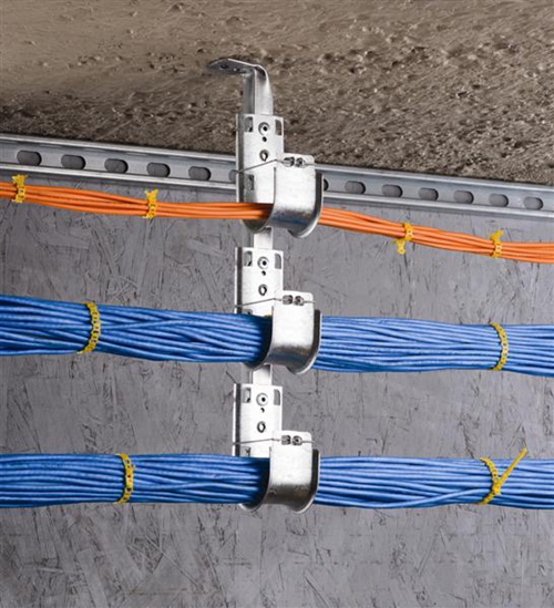
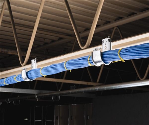
J-Hook is a common kind of fastener, usually made of galvanized steel but sometimes of plastic polymers, that is designed for giving support and management to the massive cables, so that the cables can be protected well and the performance of the high density network can be ensured or even improved. From the following figure, it is easy to find that the J-Hook has a J structure as its name implies. This J design with smooth beveled edges allows a large bending radius for cables, which also facilitates the cable installation. As for its application, you can learn it from the figure below that the orange and blue Ethernet cables are simply put on the J-Hooks and supported by the J-Hooks. You can mount it both in indoor and outdoor for managing and supporting the cables.
Installing J-Hook is as easy as using cable tie to manage the cables, which is very easy to acquire. Firstly, choosing a proper kind of J-Hook, which relies on where the J-Hook would be installed. Common locations J-Hook would be installed are wall, stud, beam, flange and drop-wire. Secondly, aligning snap lock attachment of J-hook with holes of the chosen bracket and snapping J-hook into position. Thirdly, ensuring that the intervals between J-hooks is about 1.2 m to 1.5 m. Fourthly, putting the cables in the J-hooks like the blue Ethernet cables in the figure above. And finally, checking the whole installation to see if the cables are managed well or if there is anything else wrong. If there is a need, just improving the installation to ensure the performance of the cables.
After knowing the procedures of how to mount the J-Hook, you may feel confused about the types of J-Hooks and which type is suitable for your application. In fact, there are some commonly used J-Hooks fitted with different attachments, J-Hook with angle bracket, J-Hook with beam clamp, J-Hook with hammer-on clip and J-Hook with wire/rod clip, which can be flexibly used. As for the structural differences of these four common J-Hooks, you can take the following figure as a reference.
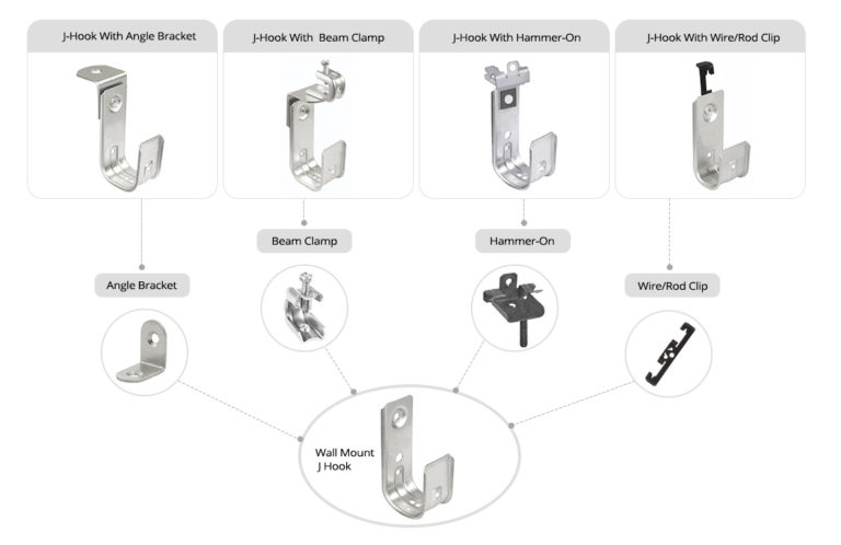
J-Hook with angle bracket can be mounted in the ceiling, which is also a cost effective solution for the cable tray. As for the attachment of the 90-degree angle bracket, in can be easily installed or removed to meet your requirement. The second type, J-Hook with beam clamp, can be fasten to the horizontal flange that allows for up to 1/8 inch flange thickness. Unlike J-Hook with angle bracket, it can be rotated 360 degrees to support all directional cable runs. As for the J-Hook with hammer-on clip, it also features swiveling 360 degrees for various direction installation. Meanwhile, it can be fast mounted by the use of the hammer. As for the fourth type, its attachment is the wire/rod clip which is very similar to the bat wing, so it is also referred to as bat wing clip. The J-Hook with wire/rod clip can be attached to various structures with its bat wing clip.
In contrast to the traditional pathway elements, J-hook is easier and faster to install and move on-site that doesn’t need any special tool. Definitely, it is an good solution with high flexibility and ease of installation for horizontal cabling support, which is also cost effective with fewer logistical demands, less installation labor and lower material cost. Meanwhile, we can also learn from this paper that J-hook features several kinds of attachments that enables itself to be installed in different applications. Due to these advantaged, there is no doubt that J-hook will be used for more and more cabling networks.
Posted by: katherinewangfs at
02:48 AM
| Comments (8)
| Add Comment
Post contains 759 words, total size 6 kb.
February 16, 2017
In recently years, more and more data centers and server rooms feature high density and large capacity, in which there are a large number of copper or fiber patch cables used for connecting the whole network. In order to ensure the performance of the whole network, there is no doubt that these patch cables should be connected with no error. Any improper cable management would directly result in cable damage and network failure that can cause data transmission error, performance issue and system downtime. But the fact is that the work of managing these massive patch cables is a quite difficult task, which is easily in error. Then what can we do to achieve good cable management and ensure network performance? This paper will mainly study the cable lacing bar, which is designed for achieving good cable management.
It is well known that cable ties (like nylon cable ties and velcro cable ties), patch panels (like copper patch panels and fiber patch panels) and J-Hook enables better cable management in high density network, which can be also found it in my last paper. Except these tools, is there any other tool that can also achieve good cable management? The answer is cable lacing bar in this paper, which is as important as the previous three tools mentioned above.
The cable lacing bar, also known as lacer bars, is a common kind of cable management tool, made of metal material, which offers support and and management of the massive patch cables. With the use of cable lacing bar, the pressure created by the cable connections can be greatly relieved, the bend radius of the patch cable can be stably controlled and the cabling can be highly improved to a neat one. At present, there are various kinds of cable lacing bars with different features to satisfy the increasing requirements of cabling network, for instance, round lacing bars, rectangular lacing bars, round lacing bars with Offset and l-shaped lacing bars, etc. For the structure of common cable lacing bar, you can learn it from the following figure.
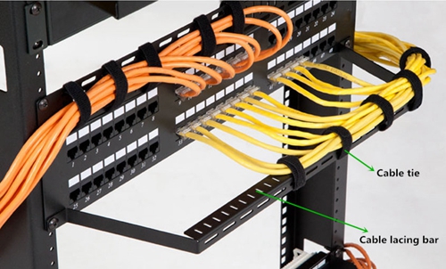
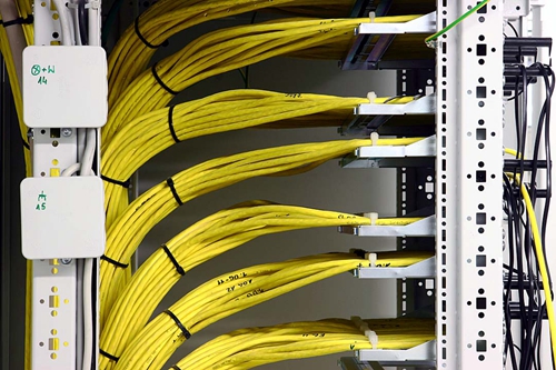
In general, the width of the cable lacing bar is always 19 inches, while its height can be alternative, 1U or 2U. It can be mounted above, below, behind, or in front of your network devices, easily found in racks (between switches and patch panels) or enclosures. As for its practical application, you are highly suggested to bind the patch cables to the cable lacing bar by the use of cable ties like black velcro cable ties in the figure above. You only need to mount the cable lacing bar to the rack, and then use the cable tie to bind the patch cables to the cable lacing bar.
What makes the cable lacing bar so widely used for managing the patch cables? Compared to other cable management tools, what are the advantages of the cable lacing bar? Firstly, using the cable lacing bar to manage the patch cables can greatly save space, because it uses less than 1U space, or doesn’t occupy any space if installed in front of or behind your network device. Hence, the valuable space can be saved for installing other network devices. Secondly, there are numerous cable lacing points, almost covering the whole cable lacing bar, which enables easier cabling. Thirdly, the cable lacing bar can relieve the strain of cables which plays an important role in high density cabling network. Fourthly, it can promotes the bend radius of the patch cables, so that the risk such as slower data transmission rates or broken patch cables can be reduced or even avoided.
As we move to more and more complicated network, the cable management takes an much more important role than ever before. With the advantages of relieving pressure created by the cable connections, promoting the bend radius of the patch cables and saving space, the cable lacing bar is an ideal choice for efficient and neat cable routing. Hence, it would be better to choose a suitable kind of cable lacing bar to manage your patch cables if your network features high density and large capacity.
Posted by: katherinewangfs at
03:23 AM
| No Comments
| Add Comment
Post contains 703 words, total size 5 kb.
February 11, 2017
As we move to more and more complicated network, the cable management becomes much more difficult than ever before. If there is something wrong in the cable deployment or management, the system downtime may occur that directly affects the productivity and efficiency of the system. Meanwhile, if the cable is not well managed, the whole system will look very dirty, disorderly and bad. In order to solve these issues, several solutions are put forward to make the cable management faster and easier and maximize the performance of the system, such as, zip tie, patch panel, J-Hook, etc. In this paper, it will mainly study these commonly used cable management tools for deploying a sophisticate, but stable and tidy cabling network.
Zip tie can be also called cable tie or wire tie that functions as a fastener for holding cables or wires together. Compared to other cable management tools, zip tie is very cheap and easy to be used. Hence, it can be easily found in a wide range of applications for managing the cables. At present, there are various kinds of zip tie available on the market, for instance, velcro zip tie that can be reusable and adjustable to support frequent moves, adds, and changes of cables, and the stainless steel zip tie that can be used in the extremely cold, hot or corrosive application. To better know the function of the zip tie, you can learn it from the following figure, in which the black zip ties play a vital role in better cable management.
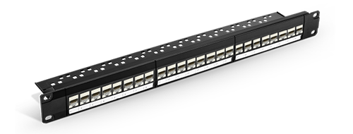
Patch panel, also referred to as patch bay, patch field or jack field, is a crucial unit in the wired network that consists of a number of similar or same jacks, with the aim of connecting and routing circuits for monitoring, interconnecting, and testing the circuits in a convenient, flexible way. In general, it can be simply divided into fiber patch panel and copper patch panel. Although the fiber patch panel is more expensive than the copper one, both of them have their own advantages and disadvantages. Therefore, you can just choose the more proper one to deploy your cabling network, enabling the ease of cabling network management and avoiding the data transmission error or failure. In addition, here offers a figure that shows the structure of 24 port Cat 6 patch panel for your reference.
As we all know that there are some widely used tools for hanging and supporting the cable bundles like zip tie and brindle ring. However, once these narrow-base kinds of fasteners exceed the bend radius of the cables, it may cause network failure. Hence, experts turn to J-Hook to solve this problem, as a cost effective solution. What should be noted it that the horizontal cabling tray is also designed for dealing with this problem, but it is not recommendable for its higher cost and taking more time for installation than J-Hook.
J-Hook, usually made of galvanized steel or sometimes of plastic polymers, can be installed in both indoor and outdoor. From its name, it is easy to learn that its structure is like the letter "Jâ€. You can also learn it from the following figure. This design of a wide base with smooth, rounded corner has the ability to effectively eliminate the potential for snags during installation, while preventing the cable bundle from stress as shown below. Due to the advantages mentioned above, it is highly suggested to choose J-Hook to manage the cable bundle.
There is no doubt that well organized cable management can make the network maintenance easier and faster, ensure the maximum performance of the network and reduce or eliminate the network connection errors and failure. It is really worthy choosing the proper cable management tools for better cable management. In addition, except for the three tools mentioned above, there are other kinds of tools like cable manager and cable lacing bar can be also used to manage the cable in better organization. Hope the information in this paper would be useful for you to deploy a neat and high performance network.
Posted by: katherinewangfs at
02:50 AM
| No Comments
| Add Comment
Post contains 692 words, total size 5 kb.
February 08, 2017
It is well known that there are various kinds of connectors used to terminate the fiber optic patch cables, such as LC, SC, FC and MTP/MPO connector. As for terminating the copper based patch cables widely applied in home wired network, there are also several RJ-style connectors published like RJ11, RJ12, RJ21, RJ35 and RJ45 jack, etc. Among these jacks, the RJ11 and RJ45 jack are the most commonly used jacks that have common in appearance, which may be not easy to tell. Since the RJ45 jack is specially designed for terminating the Ethernet patch cable like Cat 5e cable and Cat 6 cable, do you wonder that can the Cat 5e cable or Cat 6 cable be also terminated by RJ11 jack? Let’s study the RJ11 and RJ45 jack information and find the differences of these two jacks, then seek the answer.
"RJ†is the acronym of "registered jackâ€, which is a standardized telecommunication network interface designed to connect voice and data equipment to a service provided by a local exchange carrier or long distance carrier, first published by the Bell system and managed by the Federal Communication Commission(FCC). As for the number 11 and 45, they stand for different types of the registered jacks for easier and better identification.
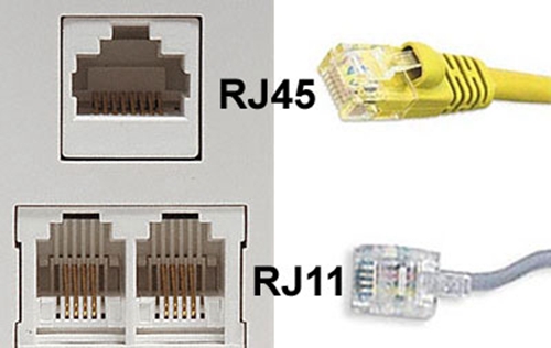
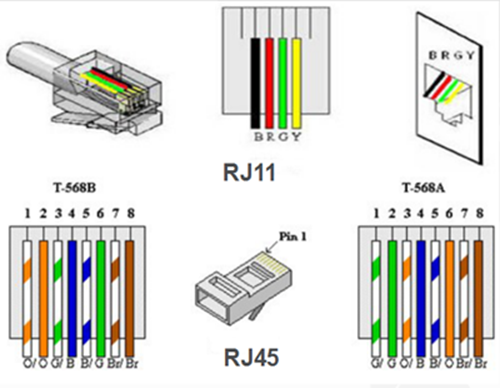
RJ11 jack, sometimes a 6P2C (6-position, 2-conductor) connector but mostly a 6P4C connector, is specially applied for telephone lines, while RJ45 jack is a 8P8C modular connector used for terminating twisted-pair cables in Ethernet network. In a typical 6P4C RJ11 jack, only four out of the six positions are generally used to terminate phone lines and the rest two are idle, but the eight positions in the RJ45 jack will be taken fully use of, four for sending and receiving data and the other four for other technologies or power networking devices, as shown in the following figure. If you want to use these two types of jacks to terminate the telephone line or the Ethernet cable, please do it in accordance with the instructions for correct terminations. Besides, it should be noted that the Ethernet cables like Cat 5e cable and Cat 6 cable can be also referred to as RJ45 cables since they can be terminated by the RJ45 jacks.
Although the RJ11 and RJ45 Jack seems very similar in appearance, but they do differ from each other in the structure. Firstly, it is obvious that there are differences in their internal structures. If you check the jacks which are connected with wires, you’ll find that there are four wires in the RJ11 jack but eight wires in the RJ45 Jack. As a result, the RJ45 Jack is generally bigger than RJ11 jack. Secondly, an typical RJ11 jack has six pins but only four of the pins in the middle are participated to connect the four wires, while there are eight pins in an RJ45 jack and both of them are used for cable termination.
Meanwhile, these two jacks have different wiring schemes, which you can learn from the figure below. As for the wiring scheme of the RJ11 jack, you can take the POTS (plain old telephone lines) residential telephone wiring as a typical example that generally contains two pairs of wires, which are designed for two separate telephone lines. And the center pins (red and green) contain the first telephone line, while the black and yellow pins contain the second one. As for the RJ45 jack, there are two wiring schemes, T-568A and T-568B, each of which can be applied in making cross-over cable or straight-through cable. A cross-over cable is terminated with an RJ45 jack used T-568A wiring scheme in one end of the cable and another RJ45 jack used T-568B wiring scheme in the other end, while the straight-through cable is terminated with two RJ45 jacks with the same wiring scheme, T-568A or T-568B.
Moreover, the biggest difference between these two jacks is their application. As for the RJ11 jack, it is the cable connector that is used in telephone sets, ADSL, and modem cables, etc. However, the RJ45 jack is designed with the aim of terminating Ethernet patch cable in networking, where you connect computers or other network elements to each other.
After knowing the basic information of the RJ11 and RJ45 jack and analyzing the differences between these two kinds of jacks, it is simple and clear that neither Cat 5e cable nor Cat 6 cable can be terminated with the RJ11 jack. Why? As mentioned above, the RJ11 jack is smaller than RJ45 jack and there are only six pins to terminate the wires in the Cat 5e cable or Cat 6 cable. Therefore, if we use the RJ11 jack to terminate the Ethernet patch cable that generally has eight wires, there will be two wires that can’t be terminated and work normally. What’s more, these two kinds of jacks are designed for different applications. As the RJ11 jack is used for terminating telephone line and RJ45 jack is to terminate Ethernet patch cable in networking, only choosing the proper jack can the performance of the telephone line or the Ethernet patch cable can be ensured.
Posted by: katherinewangfs at
09:38 AM
| No Comments
| Add Comment
Post contains 896 words, total size 6 kb.
February 05, 2017
As the network develops fast, the form of the network is gradually migrated from wired connection to wireless connection, meeting the increasing needs of the network. Does the wireless connection perform better than the wired one? Are you still hesitating over which connection should be choose to deploy your network? In this paper, it will mainly study the basic information of the wired and wireless connection and find which one is better by comparing these two kinds of network connection, giving you the answer you may care about.
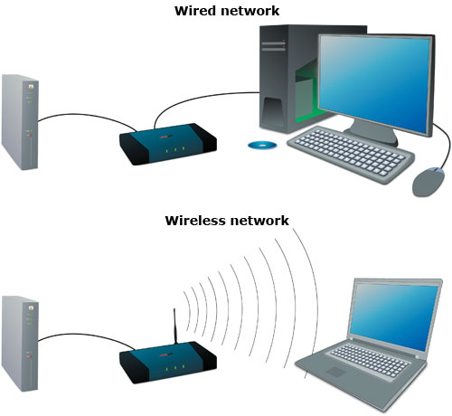
As their names imply, the wired network is deployed by using the network patch cable to connect all the devices in the wired network, while the wireless network utilizes radio waves and/or microwaves to sustain interaction channels linking computers, as shown in the following figure. Generally, both of the two forms of network have their own features, which will be introduced below.
In a wired network, network patch cable is taken full use of to connect one computer with another one or the central device in the network, and there are also other vital devices required like network adapter, hub, switch, or router to deploy further connection. As for the operation, the wired network always use the dial-up way to connect to the Internet and the computer hosting the modem has the ability to administer the Internet Connection Sharing or similar software to share the connection with every other computers on the same wired network. Compared with the wireless network, it will use broadband router that allows easier sharing of cable modem or DSL Internet connections, furthermore the broadband router often includes built-in firewall.
As for the wireless network, it is an additional recent substitute to the wired network that depends on copper and/or fiber optic cabling, which can be deployed easier and faster than the wired one. In its working process, the data is transmitted by radio waves and/or microwaves instead of through the copper and/or fiber optic patch cable. Although the cost for wireless deployment is high, this kind of network is promptly acquiring popularity for home networking because of its convenience. In addition, the most gratifying thing is that the prices of wireless commodities continue to fall as the wireless technology advances fast in recent years.
There is no doubt that the wireless network is very easy to deploy which makes it more and more popular recently. However, there are still many people who would like to choose the wired connection for their network. Why? Doesn’t the wireless network operate better than the wired one? What’s the advantages and disadvantages of these two kinds of network?
When talking about the advantages of the wired network, it is not very difficult to find that the wired network transfers the data information more swiftly and performs more securely and stably than the wireless one. Meanwhile, the devices to deploy the wired network are also not so expensive as that of the wireless one. If one cannot afford the cost for the wireless network deployment, the wired network is still a very good choice. Besides, most of the computers on the market have the wired network adapters that makes the wired network deployment convenient.
However, there are also some disadvantage that should be paid attention to when deploying the wired network. First and foremost, running the wires from one room to another within the home can be a difficult task and the network patch cables would be easy to disorganized in the installing process. And when one network patch cable in the network disconnects or becomes faulty consequently, it will cause the whole connection to fail. Furthermore, if more computers are needed to be connected to the wired network, it may result in unexpected expense. What’s worse, if it run out of the connections on your network, it could slow down the network.
After knowing the advantages and disadvantages of the wired network, let’s talk about the same topics of the wireless network. As for its advantages, it would be very neat and clean without untidy network patch cables and of high flexibility around the home for the connections around the house within a limited range. Meanwhile, it is very easy to be deployed. Even if you haven’t a great deal of networking experience, you can set up a wireless network by yourself very fast. Also, there are three main disadvantages if you choose to deploy the wireless network. Firstly, the biggest drawback of setting up a wireless home network is the high cost as mentioned above. Secondly, the potential for radio interference due to weather, other wireless devices, or obstructions like walls exits, which may make the connection wrong or failed. Thirdly, it is not so reliable as the wired network. Once one major section like the router breaks down, the whole network will be affected.
The wired network transfers the data information more swiftly, performs more securely and stably and costs lower than the wireless network, although it is not so neat, flexible and easy to deploy as the latter one. If you want to own a fast, secure and stable network, you are highly suggested to deploy the wired connection for your network. Besides, Ethernet cable for sale at FS.COM can meet your requirement to deploy the wired network, such as, cat 5e, cat 6, cat 6a and cat 7 cable. Of course, if you’d like to own a very neat network, the wireless network is very suitable for you that can be deployed very fast.
Posted by: katherinewangfs at
04:26 AM
| No Comments
| Add Comment
Post contains 937 words, total size 7 kb.
36 queries taking 0.0744 seconds, 90 records returned.
Powered by Minx 1.1.6c-pink.

